Domestic well-known Manufacturer of power system solutions
Enterprises that produce AC/DC power systems, PBY intelligent emergency power systems, UPS, and control and protection systems.
ABB, Siemens, Schneider's deep cooperation system suppliers.
Shanghai Genxing Electric Power Equipment Co., Ltd. was founded on March 21, 2002, with a registered capital of RMB 10.2 million. The company is located in Baoshan Industrial Park, Shanghai
Genxing Electric has a management core with modern enterprise management awareness, which gathers a group of technical talents in power system protection and control, power supply, and fully utilizes its personnel technical advantages. The use of high-tech and the creation of new technologies are the foundation for the company's development and meeting customer needs
The team will adhere to the concept of "innovation, cooperation, win-win, and service", continuously innovate and improve, with reliable quality, excellent performance, mutually beneficial prices, and high-quality services, to jointly develop and progress with users from all walks of life in society!
The PBY series products produced by the company have been put into use in Shanghai Jiao Tong University Affiliated Ninth People's Hospital (March 2008, August 2013), Jiading Maternal and Child Health Hospital (November 2011), and Huangpu Hospital of Fudan University Affiliated Obstetrics and Gynecology Hospital (April 2017), and have been operating safely to this day, receiving high praise from users
The company has also successfully completed the supply of AKOSOMBO and VOLTA bus differential protection cabinets for the 330kV WAPP Coastal Transmission Backbone Project in Ghana. The main products have been exported to more than 30 countries, including Türkiye, Jordan, Cuba and Nigeria. At present, the company has obtained a technology operation certificate issued by the Shanghai Science and Technology Commission.
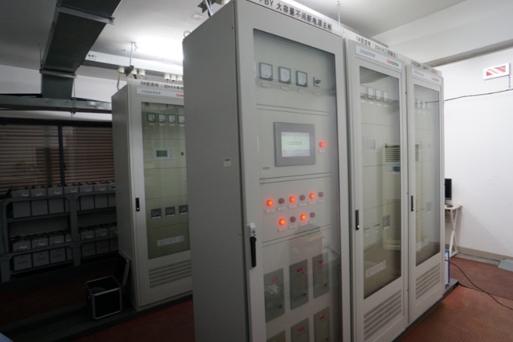
The PBY intelligent emergency power system is a product that our company adheres to the principle of reliable power supply and adopts a solution of "reliable DC" and "reliable inverter power". We have independently developed software and selected relevant hardware, and have complete intellectual property rights. It integrates many advantages of DC power cabinets (screens), UPS, and EPS, improving the reliability and practicality of the power supply
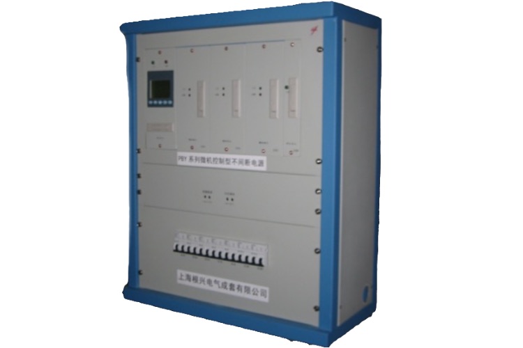
With the diversification and complexity of power loads in power systems, the demand for automation transformation of power systems in China is increasing. A new generation of intelligent microcomputer DC screens has emerged, which combines the most popular PLC/touch screen control technology in the current industrial control field with the most advanced high-frequency rectifier module in the DC screen field.
The GX-3000 substation integrated automation system is a new generation of cost-effective substation integrated automation system developed based on the successful operation of over 5000 unit equipment in more than 200 substations in the past, drawing on the advantages of domestic and foreign microcomputer protection and integrated automation technology
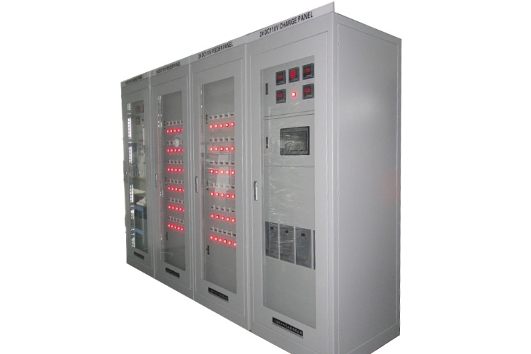
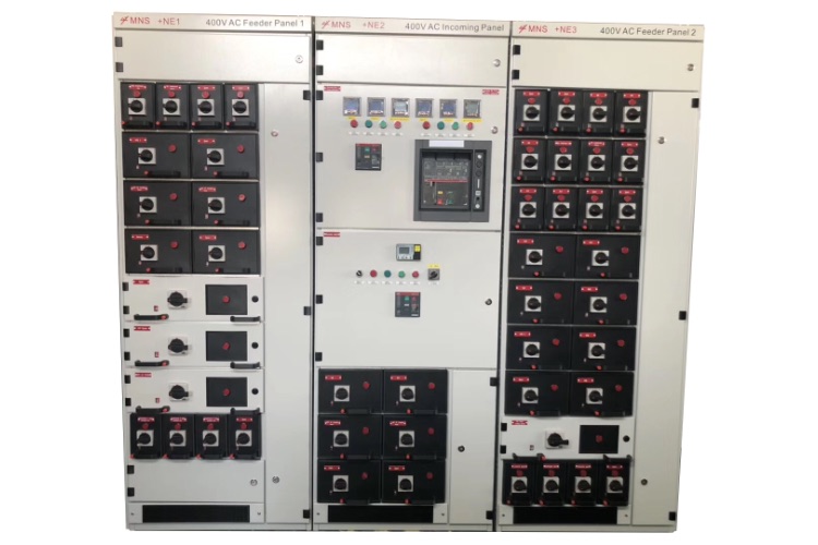
This product is a closed cabinet structure. The column adopts a modular structure with 25 as the module, which has strong universality and high standardization degree. There is a cover plate on top, side panels on both sides, and a door in front. The door is equipped with shockproof large glass, through which the operation of the component equipment can be observed. The contact between the door and the cabinet is equipped with a seal, which has good sealing performance. There are two doors behind the cabinet.
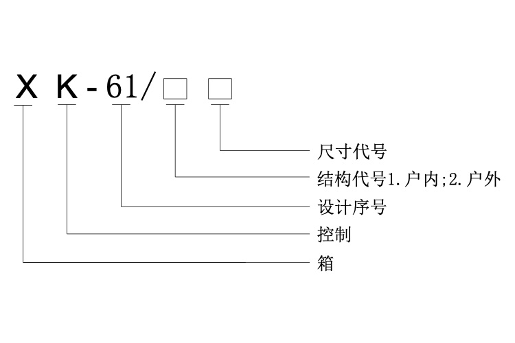
The XD-61 series power box is suitable for power supply and distribution of various capacities, as well as for power supply in workshops, buildings, machine rooms, and other places. The XK-61 series control box is suitable for remote or local control of various motors and frequency converters of different capacities.
The mosaic control screen is used in the centralized control room of a power plant to perform comprehensive functions such as centralized monitoring, control, measurement, signal indication, accident alarm, etc. for the operation of boilers, steam turbines, generators, transformers, and corresponding coal, gas, water, electricity and other equipment of the generator set
The DBJ type multifunctional signal alarm device (hereinafter referred to as the "device") is suitable for substations, power plants, wind/solar power generation, ships, oil and gas platforms, petrochemical and other systems. It is a multifunctional comprehensive alarm device that organically combines the functions of accident/warning signals, security, inspection, and reset in previous systems for centralized signal processing. For small-scale computer stations in remote areas, wireless remote transmission devices can be combined to achieve remote alarm monitoring
The instrument has high discharge power, small size, and light weight. The upper computer data management software has complete functions, greatly reducing the workload of daily battery testing and maintenance. Provide comprehensive and scientific testing methods for battery and UPS power maintenance
Professional research and development, production, and operation of power system protection and control, DC power supply and uninterruptible power supply, as well as intelligent emergency power supply system equipment
Received high praise from users
1、 Overview:
The PBY intelligent emergency power system is a product that our company adheres to the principle of reliable power supply and adopts a solution of "reliable DC" and "reliable inverter power". We have independently developed software and selected relevant hardware, and have complete intellectual property rights. It is an upgraded product that adds intelligence and AC power input interface functions on the basis of our company's PBY large capacity microcomputer controlled uninterrupted power supply cabinet product. It integrates many advantages of DC power supply cabinet (screen), UPS, EPS, and improves the reliability and practicality of the power supply. This series has an input AC voltage of 380VAC and an output AC of 220VAC or 380VAC. It mainly provides long-term AC power supply for important electric fields such as hospitals, power systems, finance, chemical industry, and industrial systems, and is an important basic equipment. Compared with the traditional diesel generator, UPS and EPS first three generation emergency backup power supply, PBY intelligent emergency power supply system is a new product in the field of AC and DC backup power supply
2、 Features and functions:
2.1 Features
2.1.1 DC system: The control part is designed with advanced programming/human-machine interface technology, which integrates various functions such as PLC, PID, data acquisition, remote control, and graphic combination into one overall system. The voltage and current collection unit adopts advanced VFC (voltage frequency) conversion technology, completely solving the problem of zero drift caused by temperature influence on the Hall sensor, thereby greatly improving the reliability of battery charging and discharging. This system is capable of intelligent charging and management, high precision of output voltage regulation, N+1 hot backup of power module, dual protection of key parts, and simple structure and convenient maintenance
2.1.2 Inverter system: Adopting mature and reliable power frequency principles, the key components are selected from the fifth generation efficient IPM power module of Mitsubishi Company in Japan, the CPU is TI Company's 2407 series DSP, and the core control components are arranged on a four layer circuit board, which has better anti-interference performance. The application of PID fuzzy control algorithm in inverter control improved the dynamic response of the system output, with TIID ≤ 4%. We also use high-efficiency transformers with imported iron cores from Japan, with a conversion efficiency of up to 94%. The inverter output adopts soft synchronization technology, ensuring a switching time of 0-4ms
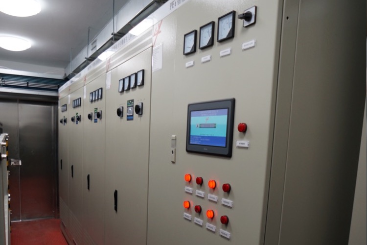
2.1.3 Monitoring system: The host adopts a large screen color touch screen, displayed in Chinese or English, and has an intuitive operating interface. The system's operating parameters are easy to set. Alarm parameters and alarm settings have security permission management and will not cause misoperation. It can also query historical records, generate reports, print and archive. Truly achieve human-machine dialogue
2.1.4 Green energy-saving: The entire equipment is usually in a system monitoring and maintenance state, and the AC power supply is directly supplied to the load through the inverter bypass. Therefore, the equipment itself consumes very low electrical energy
2.1.5 Intelligent features: It can access the internet, monitor and remotely upload all operating status and fault classification signals of the device, and can set multiple called numbers for SMS reception. If there is any abnormality in the device, it can immediately alarm, and the alarm content can be customized, making it convenient for maintenance personnel to understand the device's operation status in a timely manner. And it can check the status of various ports on the device through SMS, and the device can receive and reply via SMS
2.1.6 Special input interface of other AC power supply: after the external power supply disappears for a long time, it can be connected to other AC power supply, such as diesel generator. Theoretically, the increase of this interface can truly realize long-term uninterrupted power supply to important loads, while the external power supply supplies power to important loads through the inverter, so there is no need to worry about the input quality of external power supply, So the AC power supply to important loads is stable, reliable, and high-quality electrical energy
2.1.7 Tailored design: The PBY intelligent emergency power supply system is a product of our company with complete intellectual property rights. It can implement non-standard design based on the actual electricity usage of users and the allowed conditions for placing equipment, which can customize the required product specifications for customers. In order to better meet the actual needs of users
2.2 Function
2.2.1 System main monitoring: The operating system has multi-level menus. The displayed content includes the main schematic diagram, real-time parameters, switch positions, status quantities, fixed value parameters, fixed value modification, battery status, insulation status, etc
2.2.2 System self detection: The system can automatically alarm, monitor various classified signals such as inverter status, temperature abnormalities, mains switching, charging faults, low battery voltage, and observe fault alarms on site. In addition, it can also be remotely uploaded through the Internet and GPRS
2.2.3 System humanization function: The system supports users to customize the uploaded information content and fault alarm content (convenient for maintenance personnel to instantly understand the equipment operation status). It can set multiple SMS receiving numbers and support SMS querying of the status of various ports at that time. The system can intelligently recognize and automatically reply to SMS messages
2.2.4 System diversity communication interfaces: The system supports communication interfaces such as RS-232, RS-485, CAN, TCP/IP, network, and MODBUS protocol. All protocols are open to users. The system can record all detection data and fault status. It can also achieve functions such as "remote control, telemetry, remote adjustment, and remote signaling" through the host
2.2.5 Inverter system: The inverter system can be set with either bypass priority or inverter priority. After redesigning the cooling system, the fan can automatically recognize the ambient temperature, intelligently start and stop, achieving stepless speed regulation, reducing noise, and thus extending the lifespan of the fan
3、 Basic working principle of the system
The working principle of the system is AC → DC → inverter → AC output and AC input → inverter bypass → AC output. The schematic diagram is as follows:
The system usually uses 380V AC power supply and adopts bypass priority operation mode. The AC mains and inverter power outputs are mutually backup. Bypass output AC 380V or AC 220V for load use; The system itself will charge the battery based on the condition of the product's own battery for emergency use
Once a power outage occurs due to a power supply equipment malfunction, the system will use the stored energy from the battery to instantly output high-quality sine wave AC power, with a conversion time of less than 4ms. Therefore, it is particularly suitable for important occasions such as hospital operating rooms and intensive care units (ICUs). Taking the battery capacity of 200Ah as an example, when the load is 6600W (i.e. 220V, 30A), it can continuously supply power for more than 6 hours
When the AC power supply fault is resolved, the system can automatically recognize and switch to AC power supply, and at the same time, immediately charge the battery to make it full capacity, ready for emergency power supply again
When the external power supply disappears for a long time, other AC power supplies, such as diesel generator, can be connected through this interface. Theoretically, the increase of this interface can truly realize the long-term uninterrupted power supply to important loads, while the external power supply supplies power to important loads through the inverter, so there is no need to worry about the input quality of the external power supply, so the AC power supply to important loads is stable Reliable and high-quality electricity
5、 Technical parameters
5.1 Three phase AC input voltage 380V ± 15%, frequency 50 ± 1HZ
5.2 DC/AC power conversion blade spacing ≤ 4ms
5.3 System output AC voltage 380V 220V 110V 48V
5.4 The output AC current of the system is customized according to user needs, and can be infinitely large; Single load maximum value: single-phase 454A; Three phase load: 181A
5.5 Overload capacity: 120% rated current for 1 minute, with overload protection capability
5.6 Rated capacity level of battery: 200, 250, 300, 500, 800, 1000, 2000, 3000Ah and above
6、 Model and its meaning
The product model and its representative meaning are as follows:For example, PBY-120/800/380-1-104 PB represents: output power of 120KW, battery capacity of 800Ah, output AC voltage of 380V; The charging module is in the form of N+1 and consists of a PBY intelligent emergency power system consisting of one set of 104 valve controlled batteries
4、 Human machine dialogue operation
4.1. After the device is turned on normally, the touch screen will enter the startup screen, as shown below: (Main screen changes)
4.2. Press "Enter Main Screen" on the startup screen to enter the schematic screen, as shown below:Press "Return" in any of the above screens, and the screen will switch to the startup screen
4.3. Press "Group Battery Voltage" in the schematic screen to enter the following screen:
After pressing the ONOFF button in the picture frame, the grouped battery detection starts to run, as shown in the following image. Then, press "Enter Screen" to enter the following screen:
4.4. Press "Fault Query" in the schematic screen to enter the following screen:After entering the screen, the system's fault status will be displayed. If there is a fault in the system, the touch screen will automatically flip to this screen, accompanied by a buzzer sound output; Pressing "Alarm Release" can deactivate the buzzer sound. (Note: The fault content on the screen only pops up when there is a fault and flashes at a certain frequency.) Press the "Alarm Record" button to enter the following screen: (Main screen changes)
画面里会显示系统的历史报警记录。
4.5. Press the "System Settings" button on the schematic diagram to enter the following screen:Note: Before entering "Data Correction, Data Settings, Charging Parameters", you need to enter the administrator password. The specific operation is as follows: Press the * in the upper left corner of the screen to automatically pop up the keyboard, and then enter the administrator password in the numeric keyboard in the lower right corner of the screen. Press the ENT key, and the screen will display the current level 1 or 2, After entering the "Data Correction, Data Settings, Charging Parameters" screen to modify the data, do not forget to exit the safety level as O. Operation method: Press the number in the upper right corner of the screen to switch between levels, and directly press ENT after the keyboard appears. At the same time, the current level is displayed as 0
4.6. Press "Data Settings" in the system settings screen to enter the following screen:The above settings can be operated through the keyboard or the corresponding buttons on the right side of the screen. Keyboard operation: Clicking on a number will automatically pop up the keyboard. Enter the desired value and press ENT to confirm. Button operation: Click the corresponding left and right buttons, with the left indicating a decrease and the right indicating an increase (recommended button operation). The alarm value is in accordance with national standards. It is strongly not recommended for users to modify it
4.7. Press "Data Correction" in the system settings screen to enter the following screen:The above settings can be operated through the keyboard or the corresponding buttons on the right side of the screen. Keyboard operation: Clicking on a number will automatically pop up the keyboard, enter the desired value, and then press "ENT" to confirm. Button operation: Click the corresponding left and right buttons, with the left indicating a decrease and the right indicating an increase (recommended button operation). The 0.000 in the screen is the correction factor (actual data divided by displayed data to 3 decimal places), and the normal value is 1.000 plus or minus 1%
4.8. Press "Charging Parameters" in the system settings screen to enter the following screen:The above settings can be operated through the keyboard or the corresponding buttons on the right side of the screen. Keyboard operation: Clicking on a number will automatically pop up the keyboard, enter the desired value, and then press "ENT" to confirm. Button operation: Click the corresponding left and right buttons, with the left indicating a decrease and the right indicating an increase (recommended button operation). Warning: The batteries of the PBY intelligent emergency power supply system are customized according to the actual load requirements, and special battery plates are manufactured according to the principle of on-demand customization. Therefore, the charging curve is strictly set according to the charging curve of the special battery. The above module data adjustment has been set at the factory, and it is not recommended for non professional users to adjust, Otherwise, it may cause overvoltage and overcurrent conditions, which may damage the battery。
1. Overview
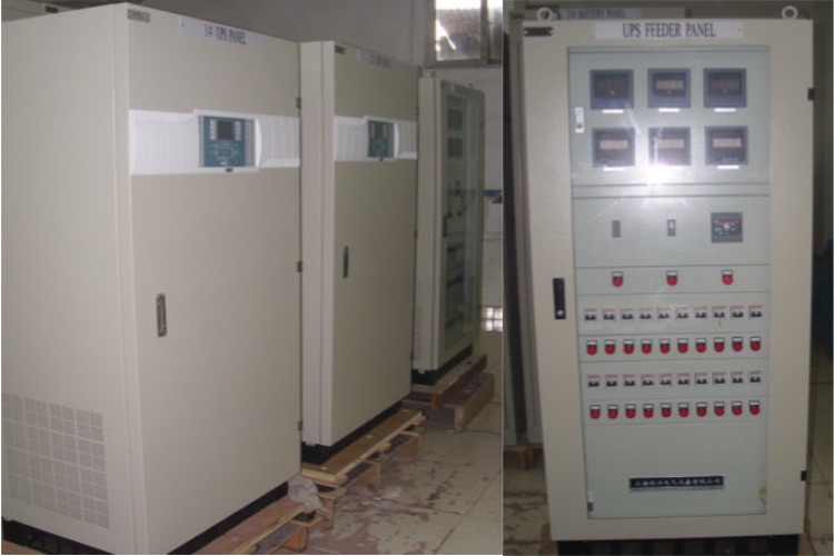
UPS converts AC energy from the power grid into DC energy and stores it in a battery. At the same time, it eliminates various clutter in the power grid and outputs pure AC power. In the event of a sudden interruption in the power grid, it can still maintain normal power supply, and electrical equipment will not shut down due to mains interference, causing significant economic losses< Especially in computer systems in industries such as telecommunications, finance, securities, transportation, and healthcare, sudden power grid outages can cause huge losses. Our company develops and produces commercial, communication, and power type UPS using imported high-speed switching power device VMOS and intelligent module IPM. It uses CPU integrated control technology, digital circuit, strong reliability, and operates online for a long time without time constraints. It converts, stabilizes, isolates, and outputs single-phase AC220V or three-phase AC380V, 50HZ pure sine wave AC power supply, uninterrupted power supply to the load, ensuring that the load is not affected by various disturbances from the power grid, Maintain normal operation. Equipped with intelligent communication interface RS232/RS485, remote monitoring is achieved without the need for dedicated personnel on site
2. Classification
2.1 Commercial dedicated UPS
Commercial UPS is mainly used in conjunction with computer systems, and generally requires stable operation, easy maintenance, less space occupation, and beautiful appearance. Therefore, our company has designed a UPS with small size, beautiful appearance, and economic practicality for this situation< This type of product is widely used in computer application systems such as household, enterprise, government office, bank, securities, railway, postal, logistics, etc
2.2 Communication specific UPS
Due to the communication department switch system, they all have their own DC 48V power supply equipment. Therefore, when designing communication specific UPS, our company adheres to the principle of saving money for users and manufactures communication specific online UPS. Its advantages are: avoiding duplicate investment in batteries, reducing system maintenance, and reducing system operating costs< This type of product is widely used in computer network management, billing systems, power monitoring, data processing, and front-end business of telecommunications, China Mobile, China Unicom, China Netcom, China Tietong, China Satcom, and China Telecom
2.3 Power specific UPS
In the substation system, it is specially equipped with a DC power supply system for electrical, thermal, closing mechanisms, emergency lighting, cooling oil pumps and other auxiliary loads. Commonly used are DC220V and there are also DC110V. Power specific UPS is specifically designed for power plants and substations (substations), utilizing an existing DC power supply system with online zero conversion function, and is technically isolated from auxiliary DC according to the system design specifications, Capable of producing single-phase or three-phase (220V/380V, 50Hz) inverter output sine wave voltage, uninterrupted power supply to the load, ensuring that the load is not affected by various disturbances from the power grid< Power dedicated UPS is mainly used for AC loads with high voltage requirements, such as DCS systems, computers, transmitters, thermal control, electrical instruments, power telecontrol, relay protection, data printing, etc
3. Model Meaning
4. Schematic diagram
4.1 Commercial UPS schematic diagramNote: If the user has a corresponding DC power supply device, the charger and battery in the diagram can be omitted and directly connected to the DC power supply device
Schematic diagram of communication type (power type) UPS
Power frequency isolation type:High frequency isolation type:
Note: DC48V is a communication specific UPS, and DC220V is a power specific UPS
1. System Overview
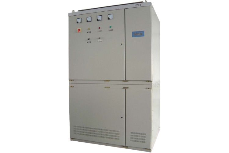
EPS is an important component of modern building safety assurance facilities. Generally, it is used as a power source for firefighting or production in emergency situations. Specially designed for firefighting equipment and primary loads (or lighting electricity). In the normal operation of the AC power grid, the AC power grid supplies power through the load of the mutual switching device, while the charger intelligently charges the backup battery. When the AC power grid is powered off or the grid voltage is below or above 25% of the rated value, the AC detection provides an inverter signal to start the inverter power supply, inverting the DC power reserve in the storage pool into stable AC power. At the same time, the mutual switching device immediately switches to the output of the inverter power supply, continuing to provide sine wave AC power to the load. When the grid voltage is normal, the emergency power supply will automatically restore the grid power supply and monitor the real-time status of the city power. When the load is a motor, EPS can perform variable frequency output based on the starting characteristics of the motor
2. Model Meaning
3. Product Features
3.1 Modular structure installation< br>
3.2 Fire linkage interface, RS232 interface< br>
3.3 Assembly of imported IPM intelligent power modules< br>
3.4 Patented technology with low no-load current< br>
3.5 INTEL's M80C196MC technology; TI C2000 series motor dedicated DSP
3.6 PLC monitoring, LCD liquid crystal display< br>
3.7 Output of isolation transformer to reliably protect user equipment< br>
3.8 The emergency output is pure sine wave AC with low harmonic content< br>
4. Schematic diagram
1. Overview
With the diversification and complexity of power loads in power systems, more and more problems have been exposed with traditional phase controlled DC screens. However, with the rapid development of digitization and microcomputerization internationally, the demand for touch screen DC screens for automation transformation of power systems in China is also increasing, A new generation of intelligent microcomputer DC screen has emerged, which combines the most popular PLC/touch screen control technology in the current industrial control field with the most advanced high-frequency rectifier module in the DC screen field. The intelligent microcomputer DC screen has made fundamental changes to the two key parts of the traditional DC screen. Its control part abandons relay circuits and single-chip circuits, and uses advanced programming/human-machine interface technology to integrate multiple functions such as PLC, PID, data acquisition, remote control, and graphic assembly, adopting a systematic solution. Its rectification part adopts an efficient hot standby high-frequency switching power supply, and uses soft switching technology to reliably convert AC power into high-quality DC power supply. This fully utilizes the advantages of contemporary computer technology and high-frequency switches in the field of DC screens, making up for the shortcomings of bulky, inefficient, and poor accuracy of microcontrollers and phase controlled power supplies< br>
The design of intelligent microcomputer DC power supply panel follows the technical standard of DL/T45P-2000 issued by the Ministry of Electric Power. Its various functions and indicators can reliably meet the power supply needs of DC control power supply and high and low voltage switch opening and closing in normal or abnormal states of the transmission and distribution system. It is widely applicable to unmanned DC power supply needs of substations below 500KV and power plants below 600000KW.
2. Features and functions
2.1 General features
2.1.1 The system monitoring unit adopts highly reliable PLC fully automatic control, suitable for unmanned places< br>
2.1.2 High reliability complete machine, power module hot backup, and dual protection for key parts< br>
2.1.3 Implement long-distance communication with the "four remote" function, and use RS232 or RS485 serial interface to easily connect to the central control unit for office automation< br>
2.1.4 Adopting a LCD touch screen with a large screen displaying Chinese characters, the operation interface is intuitive, and the system operating parameters can be easily set to achieve human-machine dialogue< br>
2.1.5 N+1 mode single module power supply, which charges the battery pack and supplies power to the control bus through electronic step-down devices and silicon chain voltage regulation< br>
2.2 DC screen network integration function
2.2.1 DC-AC inverter device: Utilizing the battery of the DC screen, it can continuously provide sine wave AC emergency power supply to the power station monitoring PC, alarm printer, general lighting, etc. in the event of AC power outage for a long time. (Normal lighting is one of the problems that UPS cannot solve, and UPS requires an additional battery to function properly)
2.2.2 DC-DC DC 48V converter: used as a backup power supply for the remote control background communication DC48V cabinet. (Can be manually and automatically controlled)
3. System composition 3.1 PLC monitoring system unit
3.1.1 The PLC monitoring system consists of two parts: hardware and software< br>
(1) Hardware
The PLC monitoring hardware consists of three parts: a PLC central controller, a sensing transmitter, and a human-machine interface< br>
① PLC central controller
The PLC central controller consists of a PLC host and two expansion modules, which are equipped with multiple I/O interfaces and dual communication ports. The host is loaded with a set of program software suitable for intelligent control of the DC screen< br>
The central control unit adopts a Japanese Mitsubishi programmable controller (PLC), which has an extremely wide power supply voltage input range (DC80V~DC300V) and strong anti-interference function< br>
② Sensor transmitter (including single battery detection device)
The function of the sensing transmitter is to collect AC/DC voltage/current external signals and transmit them to the PLC through transmission< br>
The voltage and current acquisition unit adopts the world's advanced VFC voltage frequency conversion technology, which has high precision of 12 bit conversion, complete isolation of all electrical parameters, and high anti-interference performance. The common problem of general A/D converters is that the sampling A/D of bus current and charging current needs to be isolated by adding a pre load Hall sensor, while the problem that Hall sensors cannot solve so far is the problem of thermal drift. Once errors occur, Regardless of the mode adopted by the central controller (PLC or microcontroller), it is impossible to accurately calculate the various electrical parameters that the battery needs to be charged, which can easily cause undercharging or overcharging of the battery. Therefore, the existence of the entire monitoring system is meaningless< br>
Technical characteristics of the single battery inspection instrument: It adopts imported HP linear optical coupling for collection, with high accuracy. Strong isolation, fast collection speed, and the touch screen display can be run separately from the DC screen. If an instantaneous discharge module is added, the internal resistance of a single battery can be accurately measured in real time< br>
On the basis of the basic monitoring of the original DC screen, a central signal screen function has been added. Through the access of peripheral passive signals, all functions of the previous central signal screen can be displayed and alarmed on the DC screen, saving equipment investment costs in the substation< br>
③ Human machine interface
The human-machine interface is the window and input part of PLC monitoring, which can display all the states and data during the operation of the DC screen in real time. It can directly operate the PLC input signals on the screen and add animation functions. Its external dimensions and illustrations are shown below< br>
Touch screen (various specifications)
(3) Display function
Through man-machine conversation, the screen automatically displays all dynamic processes and static data of charging and discharging, and can cancel the ammeter, voltmeter, button, indicator light and graphic identification on the traditional panel< br>
① After the power on self-test, the screen will automatically display the DC screen model and specifications, manufacturer nameplate, and relevant information, as shown on the left< br>
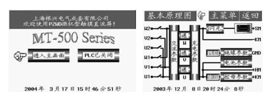 ② The main screen simulates the principle and process of the display system, displaying the current status of the system and the dynamic changes after the contacts are turned on or off, as shown in the diagram on the right< br>
③ Each sub screen simulation displays the real-time status of various parts of the charging and discharging process, including AC, charger, equalizing float charging, silicon chain, battery, insulation, temperature, flash, activation, feeder on/off, and system function settings< br>
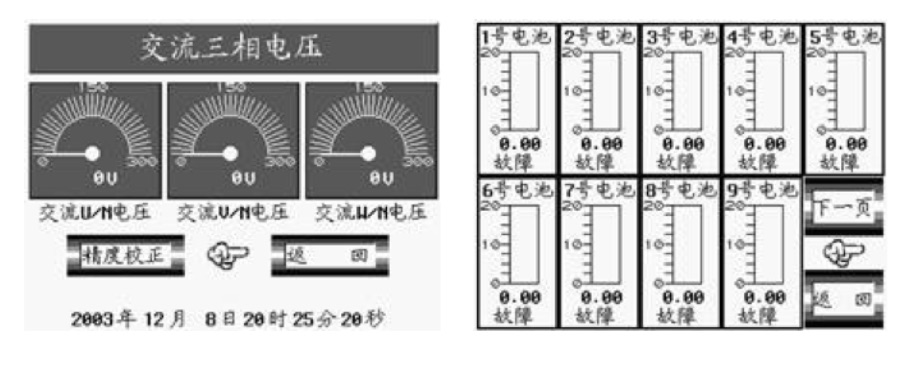
④ Quantitative display of measurement items: three-phase AC voltage, charger output voltage, battery charging voltage/current, individual battery voltage, closing bus voltage, control bus voltage/current, positive/negative bus insulation resistance value, battery cabinet temperature, temperature compensation value, grounding resistance value of each feeder, battery pack discharge capacity, activation time, alarm upper/lower limit setting value< br>
The voltage detection diagram of a single battery is shown below< br>
② The main screen simulates the principle and process of the display system, displaying the current status of the system and the dynamic changes after the contacts are turned on or off, as shown in the diagram on the right< br>
③ Each sub screen simulation displays the real-time status of various parts of the charging and discharging process, including AC, charger, equalizing float charging, silicon chain, battery, insulation, temperature, flash, activation, feeder on/off, and system function settings< br>
④ Quantitative display of measurement items: three-phase AC voltage, charger output voltage, battery charging voltage/current, individual battery voltage, closing bus voltage, control bus voltage/current, positive/negative bus insulation resistance value, battery cabinet temperature, temperature compensation value, grounding resistance value of each feeder, battery pack discharge capacity, activation time, alarm upper/lower limit setting value< br>
The voltage detection diagram of a single battery is shown below< br>
 ⑤ Display alarms for switch tripping, fuse blowing, AC phase loss, high-frequency power failure, and voltage, current, and temperature exceeding limits, displaying the type, location, and value of the fault< br>
⑥ Display of average charging curve, float charging curve, single battery charging curve, and activation curve. The charging voltage curve is shown on the left< br>
⑤ Display alarms for switch tripping, fuse blowing, AC phase loss, high-frequency power failure, and voltage, current, and temperature exceeding limits, displaying the type, location, and value of the fault< br>
⑥ Display of average charging curve, float charging curve, single battery charging curve, and activation curve. The charging voltage curve is shown on the left< br>
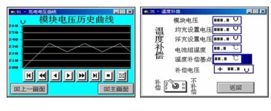 ⑦ The parameter settings and historical alarm records can be viewed, and the temperature compensation parameter settings can be viewed as shown in the diagram on the right< br>
(4) Tap input function
⑦ The parameter settings and historical alarm records can be viewed, and the temperature compensation parameter settings can be viewed as shown in the diagram on the right< br>
(4) Tap input function
① Screen or keyboard protection password input< br>
② Select the screen< br>
③ Background light adjustment< br>
④ Type in the contact signals of each control object, including AC switching, high-frequency module output, voltage reduction, equalizing floating charge conversion, flashing, activation, and other start and stop signals< br>
⑤ Set various parameters, including alarm upper and lower limits, activation time, constant charging voltage/current, etc., modify operating parameters such as conversion conditions for equalizing and floating charging, temperature compensation values, etc< br>
(5) Alarm function
① U, V, W phase power shortage/undervoltage/overvoltage alarm< br>
② Alarm for abnormal operation of high-frequency switching power supply< br>
③ High frequency power supply output voltage and current exceeding limit alarm< br>
④ Control bus voltage and current exceeding limit alarm< br>
⑤ Closing bus voltage exceeding limit alarm< br>
⑥ Charging voltage/current exceeding limit alarm< br>
⑦ Single battery abnormal alarm, indicating the location of the faulty battery< br>
⑧ Alarm for poor insulation of positive/negative busbars< br>
⑨ Feeder trip or leakage current alarm, indicating the faulty feeder number< br>
⑩ Battery pack temperature exceeding limit and over discharge alarm< br>
(6) Communication function
① Dual communication ports< br>
② Communication port definition: COM1 is an RS-232 serial communication port; COM2 is an RS-232/RS-485 (optional) serial communication port. RS-232 communication protocol: 9600BPS baud rate, even parity. RS485 communication protocol: internal< br>
③ External connection device: directly communicate with external data terminal devices; By modifying the communication protocol, integrate this DC screen into comprehensive automation communication systems such as power plants and substations; Realize remote "remote signaling, telemetry, remote control, and remote adjustment" control through MODEM< br>
(7) Storage and printing functions (Mitsubishi series)
① Store records of previous operations, faults, activations, and alarms< br>
② Equipped with printer hardware interface< br>
3.2 High frequency switching power supply
3.2.1 High frequency switching power supply
DC screens have high requirements for the reliability and stability of DC power supplies. Traditional thyristor rectifier DC power supplies have low operating frequency, large volume, high noise, and poor technical indicators and controllability due to both device and technical reasons< br>
High frequency switching power supply is an efficient and high-precision power supply using soft switching technology, which can work in parallel with multiple modules. Its battery compatibility is high, DC controllability is good, power factor is high, noise is low, current sharing is good, volume is small, DC component purity is high, and all technical indicators are far superior to traditional thyristor power supply. Due to its hard connector (hot plug board) connection method for input and output interfaces, maintenance and replacement are extremely simple, making it particularly suitable for power systems with multiple dynamic loads, high requirements for voltage stabilization, current stabilization, ripple accuracy, and N+1 redundancy configuration< br>
High frequency switching power supplies generally have two working modes: internal control and external control. In general, modules operate in external control mode, and the balance of their output voltage and current is controlled by external controllers (such as PLCs); If the external control fails and the alarm is triggered, the high-frequency power supply will switch to the autonomous charging working state, and its output voltage and output current limiting point will comply with the initial set values of the module, ensuring uninterrupted operation of the entire system< br>
The high-frequency switching power supply is mostly connected to the external using digital or analog interfaces, which is very suitable for forming an intelligent system with PLC that completely charges according to battery characteristics< br>
The comparison list between high-frequency switching power supply and traditional phase controlled power supply is as follows:
3.3 Reduced voltage silicon chain
When the DC power supply system charges the battery pack, the output voltage of the charging module will be higher than the rated voltage of the control circuit. The step-down silicon chain is connected in series between the combined busbar and the control busbar, and the voltage drop is changed by manually/automatically selecting the step of step-down to ensure that the voltage of the control busbar is adjusted within the rated range< br>
Most step-down silicon chains use PN junction forward voltage drop stacking of multiple diodes to achieve voltage drop, and the required voltage drop is obtained by changing the number of PN junctions connected in series to the circuit. Generally, 5 or 7 DC contactors are used for 5-level or 7-level control. Our company's voltage reduction device uses Darlington composite tubes to adjust the bus voltage, which increases the lifespan of the mechanical contacts of the contactors by several tens of times. The diode module is subjected to 5-level voltage reduction control, with safety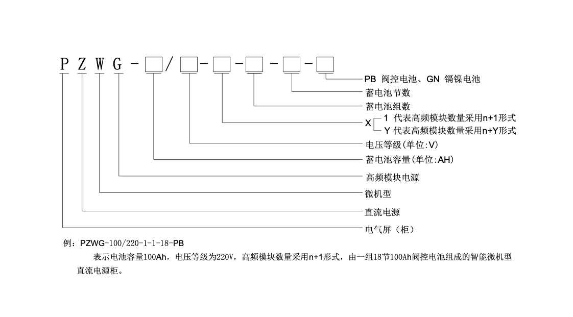
(2) Software
The PLC monitoring system software consists of two sets of logically rigorous and powerful PLC programs and human-machine interface programs. As both PLC and human-machine interface are universal products, users can independently review and modify them in an open software environment, or rewrite them. Unlike microcontrollers, which require specialized software developers to create and modify them< br>
① PLC program: used to strictly control the PLC to complete all detection, control, and communication according to logical requirements< br>
② Human machine interface program: used to configure various screens on the LCD screen to express the current status and data of each unit of the DC screen.
The principle of PLC monitoring is to ensure the continuity and reliability of the system through microcomputer processing. The electrical schematic diagram is shown below, consisting of three parts: the main circuit, control circuit, and communication circuit.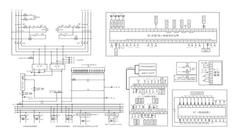
(1) Main circuit
After self switching, the two-way AC enters the high-frequency switching power supply. Under the digital or analog interface adjustment of the PLC on the high-frequency switching power supply, the high-frequency power supply strictly follows the V-T curve to perform strong charging, equalizing charging, and floating charging on the battery, and automatically performs temperature compensation and equalizing floating charging conversion according to the set conditions; At the same time, the other circuit automatically depressurizes through five levels of silicon chain and is output by bus control< br>
(2) Control circuit
By sensing the transmitter signal feedback at each node, the PLC microprocessor adopts a system integration method to comprehensively control the entire process of charging and discharging, from AC protection, rectification, compensation, equalizing and floating charging conversion, voltage reduction, activation, flashing, to restoring power transmission after the power grid is disconnected, and automatically alarms and records the PLC according to the set conditions< br>
(3) Communication circuit
The PLC has two communication ports. The COM1 port is used to communicate with the human-machine interface, transmitting all status and measurement values during the control process, including AC/DC voltage/current, temperature, insulation resistance value, discharge capacity, etc., to the human-machine interface for display, and reading the ON/OFF command and setting values input from the human-machine interface. The COM2 port of the PLC is used for remote upper computer communication< br>
3.1.3 Function
The PLC monitoring system has detection and control functions that cover all DC systems< br>
(1) Control and protection functions
① By adjusting through analog or digital ports, strictly control the high-frequency power supply to charge according to the V-T curve of the battery, automatically compensate for temperature, and switch between automatic forced charging, equalizing charging, and floating charging. Adjustable high-frequency switching power supply output voltage stability ≤ ± 0.2%, current stability ≤ ± 0.5%, ripple coefficient ≤ ± 0.1%, and adjustment accuracy of 12 bits< br>
② The power output of high-frequency power supply is limited in voltage and current, strictly preventing overcharging and undercharging of the battery< br>
③ Control the manual/automatic voltage reduction of the bus, which can support automatic control of 5 or 7 levels of silicon chains< br>
④ Manual/automatic control of battery activation< br>
⑤ Charger fault protection, including on/off, re balancing the load of the rectifier module< br>
⑥ Provide multiple normally open output contacts for relays, and the alarm items can be set by the user< br>
(2) Detection function
① Automatic detection of three-phase AC voltage (including phase loss)< br>
② Automatic detection of charger output voltage< br>
③ Automatic detection of charging and discharging currents< br>
④ The voltage and current of the control bus are automatically detected, as shown in the diagram on the left< br>
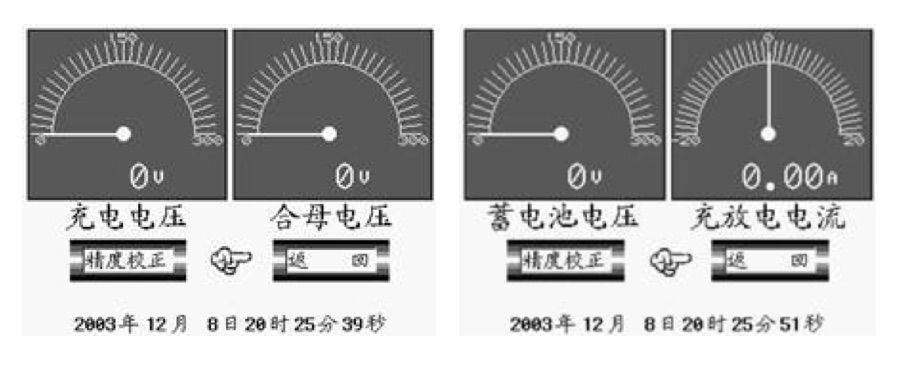 ⑤ Automatic detection of battery pack and individual battery voltage (with an expansion of up to two sets of 216 cells), as shown on the right above< br>
⑥ Automatic detection of ground leakage current between positive and negative busbars< br>
⑦ Automatic detection of battery pack temperature< br>
⑧ Feeder on/off
⑤ Automatic detection of battery pack and individual battery voltage (with an expansion of up to two sets of 216 cells), as shown on the right above< br>
⑥ Automatic detection of ground leakage current between positive and negative busbars< br>
⑦ Automatic detection of battery pack temperature< br>
⑧ Feeder on/off
(2) Software
The PLC monitoring system software consists of two sets of logically rigorous and powerful PLC programs and human-machine interface programs. As both PLC and human-machine interface are universal products, users can independently review and modify them in an open software environment, or rewrite them. Unlike microcontrollers, which require specialized software developers to create and modify them< br>
① PLC program: used to strictly control the PLC to complete all detection, control, and communication according to logical requirements< br>
② Human machine interface program: used to configure various screens on the LCD screen to express the current status and data of each unit of the DC screen.
The principle of PLC monitoring is to ensure the continuity and reliability of the system through microcomputer processing. The electrical schematic diagram is shown below, consisting of three parts: the main circuit, control circuit, and communication circuit< img src="images/plc.jpg">
(1) Main circuit
After self switching, the two-way AC enters the high-frequency switching power supply. Under the digital or analog interface adjustment of the PLC on the high-frequency switching power supply, the high-frequency power supply strictly follows the V-T curve to perform strong charging, equalizing charging, and floating charging on the battery, and automatically performs temperature compensation and equalizing floating charging conversion according to the set conditions; At the same time, the other circuit automatically depressurizes through five levels of silicon chain and is output by bus control< br>
(2) Control circuit
By sensing the transmitter signal feedback at each node, the PLC microprocessor adopts a system integration method to comprehensively control the entire process of charging and discharging, from AC protection, rectification, compensation, equalizing and floating charging conversion, voltage reduction, activation, flashing, to restoring power transmission after the power grid is disconnected, and automatically alarms and records the PLC according to the set conditions< br>
(3) Communication circuit
The PLC has two communication ports. The COM1 port is used to communicate with the human-machine interface, transmitting all status and measurement values during the control process, including AC/DC voltage/current, temperature, insulation resistance value, discharge capacity, etc., to the human-machine interface for display, and reading the ON/OFF command and setting values input from the human-machine interface. The COM2 port of the PLC is used for remote upper computer communication< br>
3.1.3 Function
The PLC monitoring system has detection and control functions that cover all DC systems< br>
(1) Control and protection functions
① By adjusting through analog or digital ports, strictly control the high-frequency power supply to charge according to the V-T curve of the battery, automatically compensate for temperature, and switch between automatic forced charging, equalizing charging, and floating charging. Adjustable high-frequency switching power supply output voltage stability ≤ ± 0.2%, current stability ≤ ± 0.5%, ripple coefficient ≤ ± 0.1%, and adjustment accuracy of 12 bits< br>
② The power output of high-frequency power supply is limited in voltage and current, strictly preventing overcharging and undercharging of the battery< br>
③ Control the manual/automatic voltage reduction of the bus, which can support automatic control of 5 or 7 levels of silicon chains< br>
④ Manual/automatic control of battery activation< br>
⑤ Charger fault protection, including on/off, re balancing the load of the rectifier module< br>
⑥ Provide multiple normally open output contacts for relays, and the alarm items can be set by the user< br>
(2) Detection function
① Automatic detection of three-phase AC voltage (including phase loss)< br>
② Automatic detection of charger output voltage< br>
③ Automatic detection of charging and discharging currents< br>
④ The voltage and current of the control bus are automatically detected, as shown in the diagram on the left< br>
⑤ Automatic detection of battery pack and individual battery voltage (with an expansion of up to two sets of 216 cells), as shown on the right above< br>
⑥ Automatic detection of ground leakage current between positive and negative busbars< br>
⑦ Automatic detection of battery pack temperature< br>
⑧ Feeder on/off detection, feeder insulation resistance value detection (with an extension of up to 64 channels)< br>
⑨ Automatic detection of battery pack discharge capacity检测,馈线绝缘电阻值检测(加扩展最多64路)。
⑨ 电池组放电容量自动检测
1. Overview
This product is designed based on the characteristics and load requirements of the battery. The product complies with relevant national standards and regulations. Due to reasonable design, advanced technology, and optimal selection of components, the reliability and stability of product use are ensured. The DC screen capacity ranges from 10Ah to 500Ah, all of which are conventional production varieties. This product can be used as a DC stabilized voltage and constant current power supply with similar load properties
2. Functions and Features
2.1 This product consists of two parts: the main circuit and the control circuit
2.1.1 Main circuit: The three-phase AC power supply is output through a choked magnetic saturation reactor and integrated module rectification, and automatically stabilizes and maintains constant current output< br>
2.1.2 Control circuit: After the three-phase AC power supply is rectified by rectification elements, a constant rectification voltage is obtained, and then amplified by the IC and oscillation signals are sent to the pulse transformer to control the conduction and blocking of the thyristor. The magnetic field changes in the choked magnetic saturation reactor are used to achieve the purpose of controlling the output current and voltage< br>
2.2 Features
2.2.1 For charging and floating charging motors of different ampere hour levels, the control board can be interchangeable with each other< br>
2.2.2 The floating charging motor serves as a voltage stabilizing source, which is not only used for the control circuit power supply, but also for floating charging the storage tank group< br>
2.2.3 The charger serves as a constant current source to charge the battery. Once the float charging motor is damaged, it can also be manually or automatically converted into a voltage stabilizing source to replace the working function of the float charging motor.
3. Usage environment
3.1 Suitable for indoor use
3.2 AC voltage fluctuation range: 380V ± 10%
3.3 Altitude not exceeding 3000m
3.4 Environmental temperature: -20 ℃+40 ℃
3.5 The daily average relative humidity shall not exceed 95%, and the monthly average relative humidity shall not exceed 90%< br>
3.6 The use site must not contain explosive media, gases that do not contain corrosive metals or damage insulation, or conductive media< br>
3.7 The place of use shall be free from severe vibration and impact, and the vertical inclination shall not exceed 5%.
4. Technical parameters
4.1 Voltage stabilization accuracy: ≤ ± 2%
4.2 Constant current accuracy: ≤ ± 5%
4.3 Ripple coefficient: ≤ ± 2%
4.4 Overload performance: 1.5In, 1min
4.5 Insulation resistance: ≥ 10M_< br>
4.6 Insulation strength: 2kV, 1min
4.7 Temperature rise:<65 ℃
4.8 Noise: ≤ 60db
5. Main data of this product
5.1 This product is a cadmium nickel battery DC screen with a capacity of 250Ah and a DC output voltage of 110V< br>
5.2 The charging current is 0.2C, which is 50A. (C is the battery capacity)
5.3 DC output voltage (control bus voltage): 110V
5.4 Adjustable range of control bus voltage: 90V~130V
5.5 Control bus load current: 50A
5.6 Local overload capacity: 115% (<60A)
5.7 Working mode: continuous working system
6. Instructions and Debugging Methods
6.1 This product has passed the debugging and inspection< br>
6.2 After long-distance transportation, the DC screen can be adjusted appropriately after installation< br>
After the installation and inspection of the product are correct, the 3-phase four wire 380V AC power supply can be connected to check for any missing phases. Firstly, put Unit 2 (float charging motor) into operation. Turn on the Q2 power switch and measure the voltage between terminals 5 (+) and 6 (-) on the ID terminal block. The voltage should be around 115V, which is the control bus voltage for the No. 3 feeder screen to supply power to the load. At the same time, the voltage between ID terminal 6 (-) and terminal 8 (+) should be measured to be 134V, which is a floating charge voltage. The battery should be floating charged to ensure self loss after supplementing the battery with full capacity< br>
6.4 The voltage of the control bus detected at this time is 115~116V on the voltmeter of the control bus in front of the screen. If it is too large or too small, it can be fine adjusted through 3RW adjustable potentiometer. If there is shaking, a load (5-10A) can be connected to the feeder screen to obtain a stable output voltage< br>
The 6.5 floating charge ammeter should display a floating charge current of around 1.25A. The adjustment range is calculated at 3-5mA per ampere hour (AH). This machine is 250AH, so the floating charging current is 1.25A. The floating charge current can be adjusted by RW adjustable potentiometer< br>
6.6 The float charging ammeter can only display the actual float charging current value after connecting to the battery< br>
After the normal operation of Unit 2, Unit 1 (charger) can be put into operation. Connect a 3-phase four wire 380V power supply and also connect the battery pack. Turn on the Q1 power switch and the Q3 charging switch, and the charger will charge the battery. The charging mode of the machine is constant current charging, with an output current of 50-52A. The charging ammeter in front of the screen should display this current< br>
6.8 If the charging current is too large or too small, it can be slowly rotated through the 1RW adjustable potentiometer to make the charging current reach the rated value< br>
6.9 Once the charger works instead of the floating charger, the control bus voltage is adjusted by the 2RW adjustable potentiometer. Measure the voltage between terminal 5 (+) and terminal 8 (-) of terminal block 2, and the voltage is about 115V at this time. The voltage between terminal 8 (-) and terminal 11 (+) should be around 134V, which is a floating charge voltage. Please refer to 6.4 and 6.5 for the method< br>
After replacing the control printed board, the control bus voltage and charging current must be adjusted accordingly< br>
6.11 When connecting the battery pack to the terminals, attention should be paid to the voltage polarity and it should not be connected incorrectly< br>
6.12 The charger charges the battery, and the battery voltage gradually increases. When the battery voltage reaches the set value of 137-138V, the charger automatically stops charging and enters standby mode. Once the floating charging machine malfunctions and there is no output voltage, the charging motor can automatically replace the floating charging machine to ensure the power supply of the control bus< br>
6.13 Manual and automatic switching switch< br>
6.13.1 The switch handle indicates the "O" position, and the charger operates in automatic mode. When the charger charges the battery and the voltage reaches the set value, it can automatically stop. Entering standby mode, once the floating charging machine fails without output voltage, the charging motor can automatically replace the floating charging motor to ensure the power supply of the control bus< br>
6.13.2 The switch handle points to the "left" position, indicating a manual forced charging state. Indicates that the battery voltage is normal and there is no need to manually start the charger to charge the battery while charging< br>
6.13.3 The switch handle points to the "right" position, indicating that the float charging motor has stopped working due to a fault. The float charging motor is replaced by a manual start of the charging motor< br>
6.13.4 Special instructions: Please do not operate under normal working conditions as stated in 6.13.2 and 6.13.3. Only when the automatic state is not working can actual operation be carried out< br>
7. Model Meaning
7、型号含义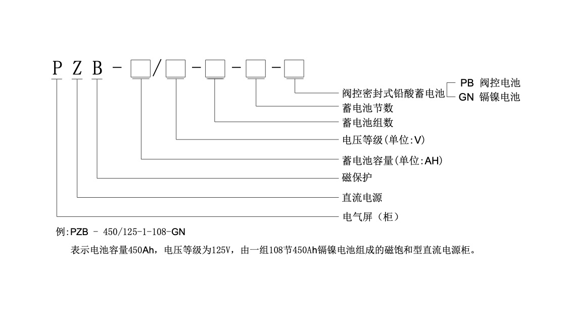
1. Overview
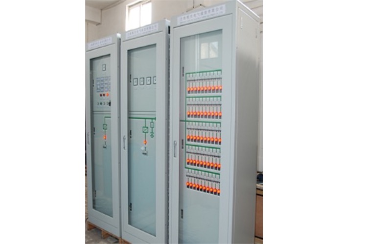
GX-BG-X1GP wall mounted power supply is designed by our company specifically for small capacity systems; Suitable for small switch stations, small user substations, and systems that adopt an integrated design concept, consisting of rectifier modules, monitoring modules, voltage reduction units, distribution units, and battery installation boxes; It has the characteristics of small size, simple structure, and independent system composition; The monitoring module adopts LCD Chinese character menu display, which has complete functions for system monitoring and battery automation management. It has four remote interfaces connected to the automation system, and provides two communication interface options: RS232 and RS485. It also provides three communication protocol options: RTU, CDT, and MODBUS.
2. System functional characteristics
Suitable for systems below 38AH/220V and 65AH/110V< br>
The module, monitoring unit, and step-down unit all adopt a live plug and drop structure, which is easy to install and maintain< br>
Three 2A/220V and 4A/110V natural cooling modules can be installed< br>
The voltage reduction unit has an automatic silicon chain voltage reduction function, with a maximum current of 2A and an impulse current of 30A/0.5S< br>
The monitor adopts LCD display, Chinese character menu, and button operation, which can achieve system parameter setting, system working parameter display, system fault indication, and system calibration< br>
The monitor has the function of automatic battery management< br>
Provide two communication interface options: RS232 and RS485, and three communication protocols: RTU, CDT, and MODBUS, which can be connected to the power station automation system< br>
The monitor realizes battery voltage, control bus voltage, control bus current, battery charging and discharging current, and module status detection< br>
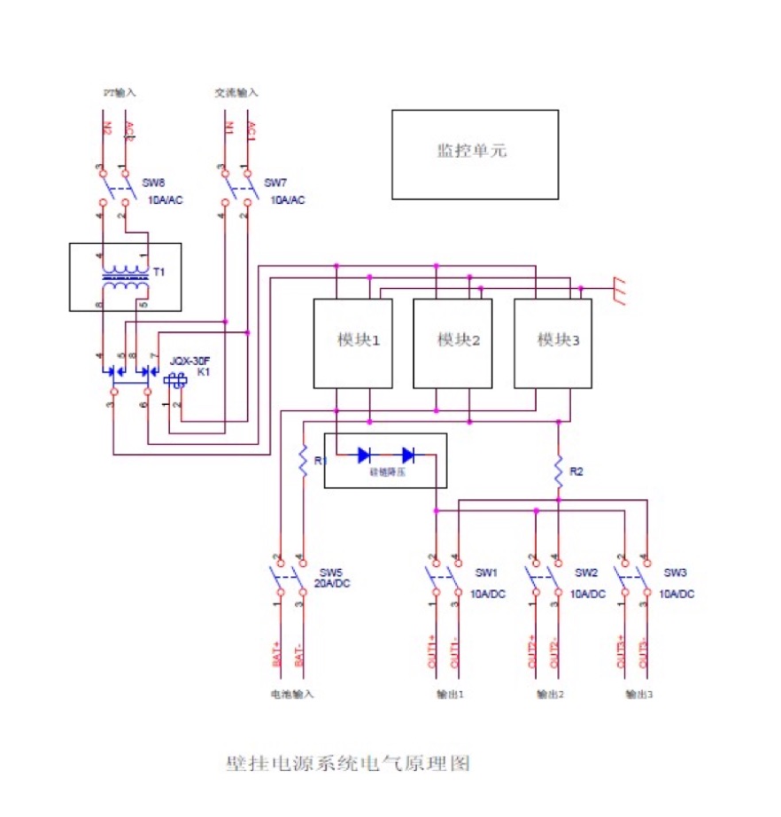
The power distribution unit provides 2 AC inputs (one PT power supply can be selected) and 3 feed outputs< br>
The system automatically limits the output power during PT power supply.
3. System technical indicators
AC input voltage: 220V ± 20%
PT power supply voltage: 100V ± 10%
Grid frequency: 50Hz ± 10%
Power factor: ≥ 0.85
Output voltage range: 90V-140V continuously adjustable (for 110V systems)
180V-280V continuously adjustable (for 220V systems)
Output current limiting: 0.2A-2.5A (single module)
Voltage stabilization accuracy: ≤ ± 0.5%
Steady current accuracy: ≤ ± 0.5%
Ripple coefficient: ≤ ± 0.1%
Average flow rate: ≤ 5%
Efficiency: ≥ 93%
Output overvoltage protection: 280V ± 2V (220V), 140V ± 2V (110V)
Insulation resistance: ≥ 10M
Insulation strength: Apply 2kV AC to output to ground, input to ground, and input to output for 1 minute without flashover or flashover< br>
Relative humidity: ≤ 90%
Environmental temperature: -5 ℃~45 ℃
Audible noise: ≤ 55db
Boundary dimension: 452 (width) × 600 (high) × 236 thick
Weight: 20kg (fully configured)
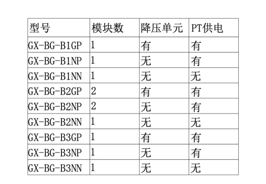
4. System model definition and configuration
4.1. System Model Definition
4.2. System Configuration Description
The system adopts a modular structure and can be flexibly configured according to user requirements. There are three output voltage specifications: 220V, 110V, 48V; There are two specifications for voltage reduction units: 110V and 220V; It can automatically switch between two AC channels, and the second AC channel can also use PT100V power supply. When the PT is powered, the output power is automatically limited to ensure the normal operation of the PT< br>
Describe the model definition using a 220V system:
 5. System electrical schematic diagram
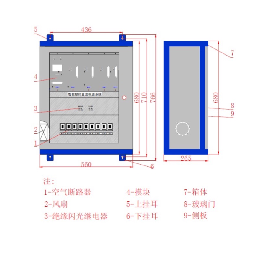
 6. System structure and overall dimensions
1. Technical parameters:
1.1 Rated parameters
1.1.1 Rated DC voltage
220V or 110V (specify when ordering)
1.1.2 Rated AC data
● Phase voltage 100/√ 3 V
● Line extraction voltage 100V or 100/√ 3 V
● AC current 5A or 1A (specify when ordering)
Rated frequency 50Hz
1.1.3 Power consumption
● DC circuit not greater than 30W
When the rated AC voltage is 100V, the AC voltage circuit should not exceed 0.3VA/phase
When the rated AC voltage is 100/√ 3 V, the AC voltage circuit should not exceed 0.1VA/phase
When the AC current is 5A, the AC current circuit should not exceed 0.3VA/phase
When the AC current is 1A, the AC current circuit should not exceed 0.1VA/phase
1.1.4 Contact capacity
● Signal circuit contact current carrying capacity 5A
● Voltage switching circuit contact current carrying capacity 5A
Signal circuit contact arc breaking capacity 60VA (DC 220V)
Voltage switching circuit contact arc breaking capacity 60VA (DC 220V)
1.1.5 Tripping and closing current
Adapted to various tripping and closing current circuits, no need to replace relays or jumpers
1.2 Main technical performance
1.2.1 Accurate working range of sampling circuit
Protection: Current 0.2In-20In (zero sequence current for small grounding selection is 0.05-1.0A)
Voltage 1V-120V (zero sequence overvoltage for backup protection is 1V-200V)
Measurement: Current 0.1In -1.2In
Voltage 1V-120V
1.2.2 Measurement of analog quantity accuracy
Current and voltage ≤ 0.3% (excluding main CT and PT errors)
Power ≤ 0.5%
Frequency ≤ 0.01Hz
Power factor ≤ 0.01
1.2.3 Protection analog quantity accuracy
Comprehensive error of current and voltage ≤ 3%
Frequency error ≤ 0.02HZ
1.2.4 Overload capacity:
The AC circuit can withstand 15 times the rated current, with an impact interval of 2 minutes and a duration of 5 seconds
Continuous operation of AC voltage circuit at twice the rated voltage
Continuous operation of DC power circuit at 70% -130% rated voltage
1.2.5 Whole set action time (including inherent time of relay)
Not more than 30 milliseconds (quick break, 2 Iset)
1.2.6 Permissible working environment
Monitoring system -4 ℃ -50 ℃
Relay protection operating temperature -5 ℃ -45 ℃
Extreme working temperature -25 ℃ -55 ℃
Relative humidity ≤ 95%
Atmospheric pressure 86-106Kpa
1.3 Insulation performance
1.3.1 Insulation resistance
Measure the insulation resistance between the live and non live parts of the device, as well as between circuits that are not electrically connected, using a megohmmeter with an open circuit voltage of 500V. Under normal test atmospheric conditions, the insulation resistance of each level of circuit should not be less than 100 megohms< br>
1.3.2 Medium strength
Under normal test atmospheric conditions, the device can withstand a power frequency withstand voltage test with a frequency of 50HZ and a voltage of 2000V for 1 minute without any breakdown or flashover phenomenon. During the test, when voltage is applied to any of the tested circuits, the other circuits are connected to each other at equal potential< br>
1.3.3 Impulse voltage
Under normal test atmospheric conditions, the device's power input circuit, AC input circuit, output contact circuit to ground, and between circuits can withstand a short time impulse voltage test of 1.2/50 µ s standard lightning wave, with an open circuit test voltage of 5000V< br>
1.3.4 Humidity and heat resistance
The device can withstand the damp heat test specified in Chapter 21 of GB7261. The maximum test temperature is+55 degrees Celsius, the maximum humidity is 95%, and the test time is 48 hours. Each cycle lasts for 24 hours during the alternating damp heat test. Within two hours before the end of the test, the insulation resistance between the exposed non charged metal parts and shells of each conductive circuit, as well as between circuits that are not electrically connected, shall be measured according to the requirements of Article 3.1, and shall not be less than 1.5 megaohms. The dielectric withstand voltage strength shall not be less than 75% of the voltage amplitude of the dielectric strength test specified in Article 3.2< br>
1.4 Electromagnetic compatibility performance
1.4.1 Electrostatic discharge reactance interference level
Passed the GB/T17626.2-1998 standard and electrostatic discharge reactance interference level 3 test< br>
1.4.2 Radio frequency electromagnetic radiation immunity
Passed the GB/T17626.3-1998 standard and RF electromagnetic radiation reactance interference level 3 test< br>
1.4.3 Fast transient pulse group anti-interference degree
Passed the GB/T17626.4-1998 standard, electrical fast transient pulse group anti-interference level 3 test
1.4.4 Surge (impact) immunity
Passed GB/T17626.5-1998 standard, surge (impact) anti-interference level 3 test
1.4.5 Conducted Disturbance Induced by RF Fields
Passed the GB/T17626.6-1998 standard and conducted disturbance level 3 test induced by radio frequency fields
1.4.6 Power frequency magnetic field immunity
Passed GB/T17626.8-1998 standard and power frequency magnetic field anti-interference level 5 test
1.5 Mechanical properties
1.5.1 Vibration
Passing the vibration capacity test with severity level I specified in 16.3 of GB/T7261< br>
1.5.2 Impact
Passed the impact capacity test with severity level I specified in 17.5 of GB/T7261< br>
1.5.3 Collisions
Passed the collision test with severity level I specified in Chapter 18 of GB/T7261< br>
1.6 Device Panel Diagram
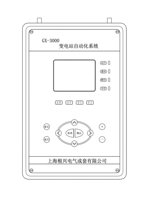 Figure 2-1 Front Layout of Unit Chassis
As shown in the picture, the front of the chassis is equipped with a LCD display screen. Work indicator light and operation keyboard. The back of the chassis is equipped with input and output terminal blocks< br>
2. Product classification:
2.1 Line protection measurement and control unit: GX-3010
2.1.1 Two phase line protection measurement and control unit: GX-3011A
2.1.2 Three-phase line protection measurement and control unit: GX-3011B
2.1.3 Segmental protection measurement and control unit: GX-3012
2.1.4 Short line differential protection unit: GX-3013
2.2 Capacitor protection measurement and control unit: GX-3020
2.2.1 Conventional capacitor protection measurement and control unit: GX-3021
2.2.2 Differential voltage capacitor protection measurement and control unit: GX-3022
2.2.3 Differential current capacitor protection measurement and control unit: GX-3023
2.3 Transformer protection measurement and control unit: GX-3030
2.3.1 Two coil transformer protection and measurement unit: GX-3031
2.3.2 Three coil transformer protection measurement and control unit: GX-3032
2.3.3 Transformer high-voltage side backup protection measurement and control unit: GX-3033H
2.3.4 Transformer medium and low voltage side backup protection measurement and control unit: GX-3033M/L
2.3.5 Transformer switch operation control unit: XWJK-3334
2.3.6 Transformer non electrical quantity protection and switch operation control unit: GX-3035
2.4 Backup power supply automatic switching unit: GX-3040
2.4.1 Incoming backup power supply automatic switching unit: GX-3041
2.4.2 Segmented backup power supply automatic switching unit: GX-3042
2.5 Distribution transformer protection measurement and control unit: GX-3050
2.6 Motor protection measurement and control unit: GX-3060
2.6.1 Motor differential protection unit: GX-3061
2.6.2 Motor comprehensive protection measurement and control unit: GX-3062
2.7 Measurement and control unit: GX-3070
2.7.1 Single line measurement and control unit (ordinary): GX-3071A
2.7.2 Single line measurement and control unit (with synchronization function): GX-3071B
2.7.3 Dual line measurement and control unit: GX-3071C
2.7.4 Common measurement and control unit: GX-3072
2.8 Voltage integrated unit: GX-3080
2.8.1 Voltage parallel unit: GX-3081
2.8.2 Voltage parallel monitoring unit: GX-3082
2.9 Communication management unit: GX-3090
1. Purpose
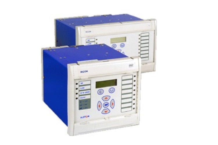
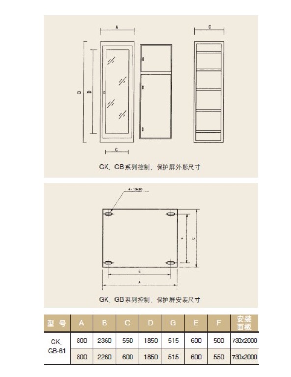
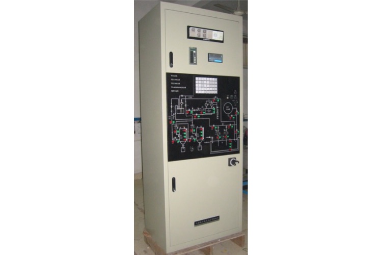
The GK and GB-61 series control and protection cabinets are suitable for various types of thermal power plants, hydropower plants, and substations with different capacities, especially large and medium capacities, as control and protection equipment< br>
2. Model Meaning
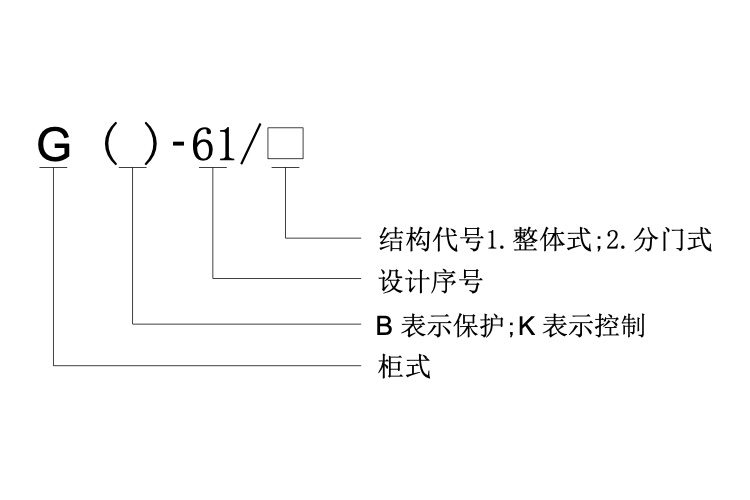 3. Structural characteristics
This product is a closed cabinet structure. The column adopts a modular structure with 25 as the module, which has strong universality and high standardization degree. There is a cover plate on top, side panels on both sides, and a door in front. The door is equipped with shockproof large glass, through which the operation of the component equipment can be observed. The contact between the door and the cabinet is equipped with a seal, which has good sealing performance. There are two doors behind the cabinet< br>
There is a mounting panel inside the cabinet, with an overall size of 730 × 2000 (2100) mm (width × High), small doors can also be opened on the installation board and fixed on the cabinet frame. The installation panel can be equipped with measuring instruments, signal lights, operating switches, relays, and relay protection devices. According to needs, a small number of resistors, fuses, knife switches, contactors, and other switches can also be installed in the cabinet< br>
According to user needs, various symbols for analog circuits can also be drawn on the installation panel using colored paint or organic glass strips< br>
The terminal blocks of this product are installed on both sides of the cabinet, and each side can accommodate 125-150 terminals. The small busbar is installed on the top of the cabinet, and can accommodate 30 small busbars, 15 upper busbars, and 15 lower busbars< br>
4. Appearance and installation dimensions (as shown in the figure below)
 5. Ordering instructions
5.1 Indicate the product model, specifications, color, and quantity. For example: GB61/1 2360 × eight hundred × 600, Z44 light camel, one set< br>
5.2 Provide a complete set of engineering drawings (including screen layout diagram, schematic diagram, small busbar layout diagram, terminal strip diagram behind the screen, etc.)< br>
5.3 If a side screen is required, specify the quantity and color markings on the agreement< br>
5.4 Special specifications can be negotiated face-to-face< br>
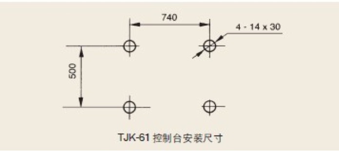
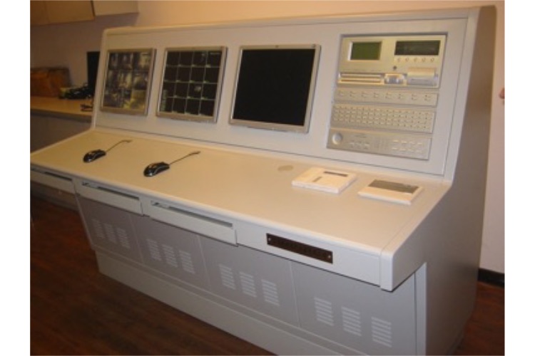
Purpose
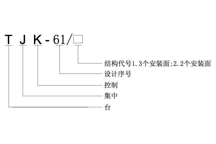
The TJK-61 series centralized control console is a new type of control equipment used in the central control room of power plants and substations. It can perform centralized operation, control, and monitoring of the operation of power plant and substation transmission and distribution equipment, and is also suitable for centralized control of industrial, mining, and enterprise production processes< br>
2. Model Meaning
 Structural characteristics
The 3.1 TJK-61 series centralized console is a modular body, with a single body width of 800 mm. The entire console can be spliced according to the number of sections required by users and formed on the second side panel. The console panel can be flipped up at a 70 ° angle to the body, making it easy to inspect or replace any components on the panel< br>
3.2 The central control console has three installation slopes (as shown in the diagram). The first installation surface is the main operating surface, which can be used to install control switches, buttons, and signal lights. The second installation surface can be used to install display elements such as light plates. The third installation surface can be used to install various measurement registration forms, accident clocks, frequency meters, and other components< br>
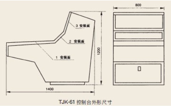 4. Appearance and installation dimensions (as shown in the figure below)
 5. Ordering instructions
5.1 Number of central control console units< br>
5.2 The color of the table and the color of the table can be determined according to user requirements< br>
5.3 Provide table layout diagram, control schematic diagram, and terminal strip diagram.
Purpose
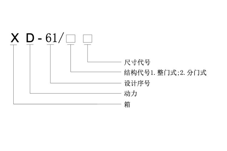
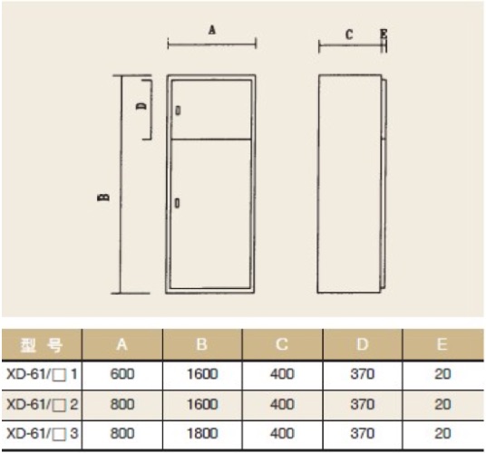
The XD-61 series power box is suitable for various capacities of power supply, distribution, and is a power source for workshops, buildings, machine rooms, and other places< br>
2. Model Meaning
 Structural characteristics
The front door of the box can be divided into two parts, and the door can be equipped with control components such as metering meters, control switches, buttons, and signal lights. Components such as knife switches, circuit breakers, contactors, relays, etc. can be installed inside the lower door< br>
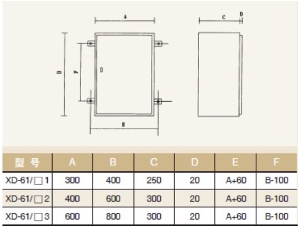
4. External dimensions (as shown in the figure below)
 5. Ordering instructions
5.1 Indicate the product model, specifications, color, and quantity< br>
5.2 Provide a complete set of engineering drawings< br>
1. Purpose
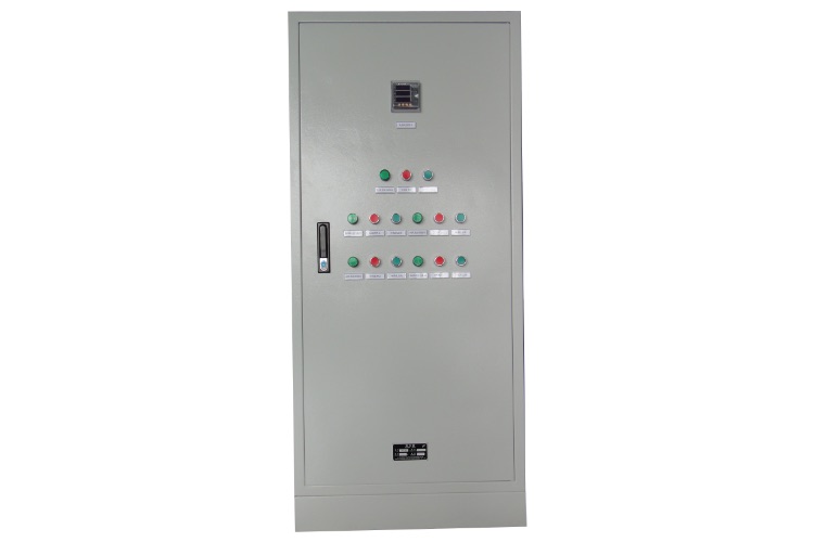
The XK-61 series control box is suitable for remote or local control of various motors and frequency converters of different capacities< br>
2. Model Meaning
 3. Structural characteristics
There is a detachable mounting plate inside the box, which can accommodate an appropriate amount of circuit breakers, contactors, thermal relays, and control relays. The board can be equipped with components such as electricity meters, switches, buttons, signal lights, etc., for on-site control purposes< br>
The outdoor control box is equipped with a double-layer installation board, and the components are installed on the inner board to prevent rain and wind erosion. The outdoor type is mainly column mounted, while the indoor type is wall mounted< br>
4. External dimensions (as shown in the figure below)
 5. Ordering instructions
5.1 Indicate the product model, specifications, color, and quantity< br>
5.2 Provide a complete set of engineering drawings< br>
1. Purpose
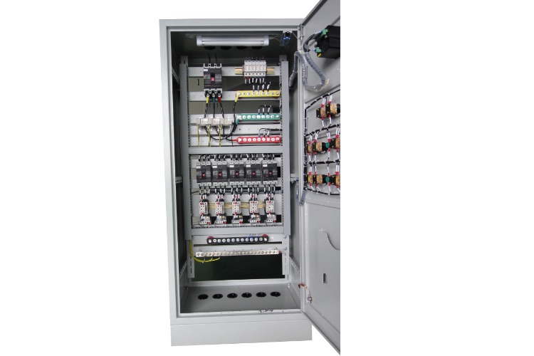
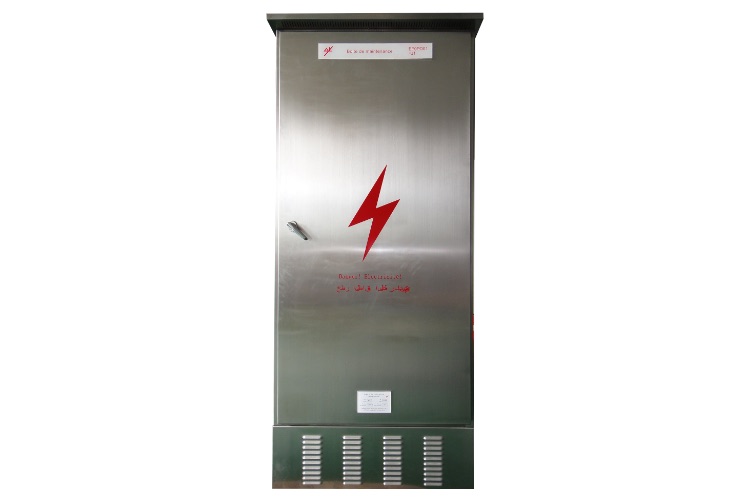
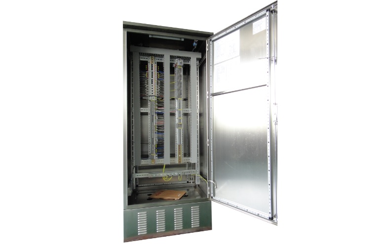
Suitable for local control and cable transfer in power plants and substations of 35KV, 110KV, 220KV, 500KV and below< br>
2. Model Meaning
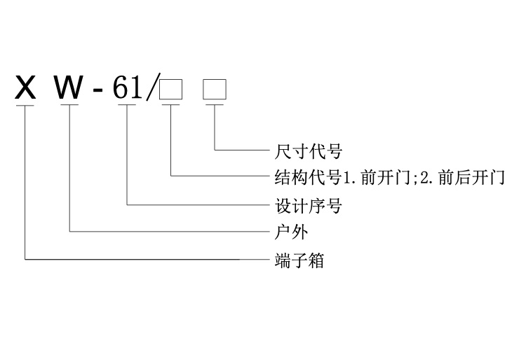 3. Structural characteristics
3.1 It is made of high-quality stainless steel material and can be opened back and forth< br>
3.2 The outdoor terminal box adopts a top hat method, and the door frame is sealed to prevent rain, water, and dust. Additionally, a louver base is added for easy ventilation and drying, while also preventing small animals from entering< br>
4. External dimensions (as shown in the figure below)
 5. Ordering instructions
5.1 Indicate the product model, specifications, color, and quantity< br>
5.2 Provide a complete set of engineering drawings< br>
1. Purpose
The mosaic control screen is used in the centralized control room of a power plant to perform comprehensive functions such as centralized monitoring, control, measurement, signal indication, accident alarm, etc. for the operation of boilers, steam turbines, generators, transformers, and corresponding coal, gas, water, electricity and other equipment of the generator set< br>
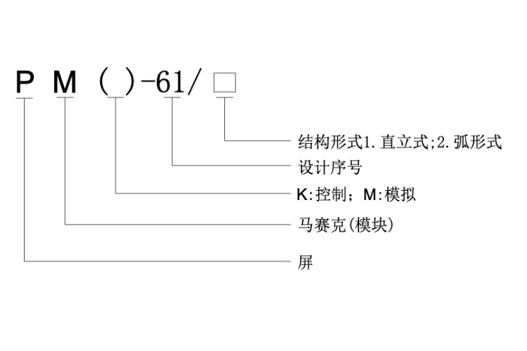
2. Model Meaning
 3. Features
3.1 The PMK (M) -61 screen frame is processed using high-precision imported machine tools, with fine craftsmanship and a beautiful mosaic panel shape. The disc adopts an overall sealing structure, and multiple sets of double doors are designed behind the disc (one set below 1000). The lighting inside the panel is controlled by the automatic opening and closing switch of the door< br>
3.2 The mosaic module adopts imported flame-retardant plastic injection molding, and the module is spliced into a disk surface by Yanni tenon. The disk combination is flexible, with insulation, flame retardancy, and long-term non discoloration performance< br>
3.3 Mosaic module with 25 × 25 mm is the modulus, and the panel can basically install various measuring instruments, recording instruments, industrial televisions, digital displays, control switches, display lights, alarm devices, and other equipment at will, facilitating the balanced layout of the panel< br>
3.4 The system pattern adopts concave engraving technology or light strip form, with bright color and firm coloring< br>
3.5 Changing the system (updating equipment) only requires partial disassembly and assembly of modules< br>
3.6 PMK (M) -61 is made of high-quality materials, and its price is only 40% of that of similar imported products< br>
4. Structure
4.1 Mosaic control screen, the screen can be arranged in an arc shape, with an arc radius of 8-15m< br>
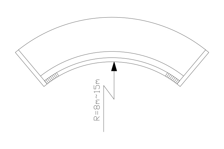 4.2 The appearance and installation dimensions are shown in the following figure:
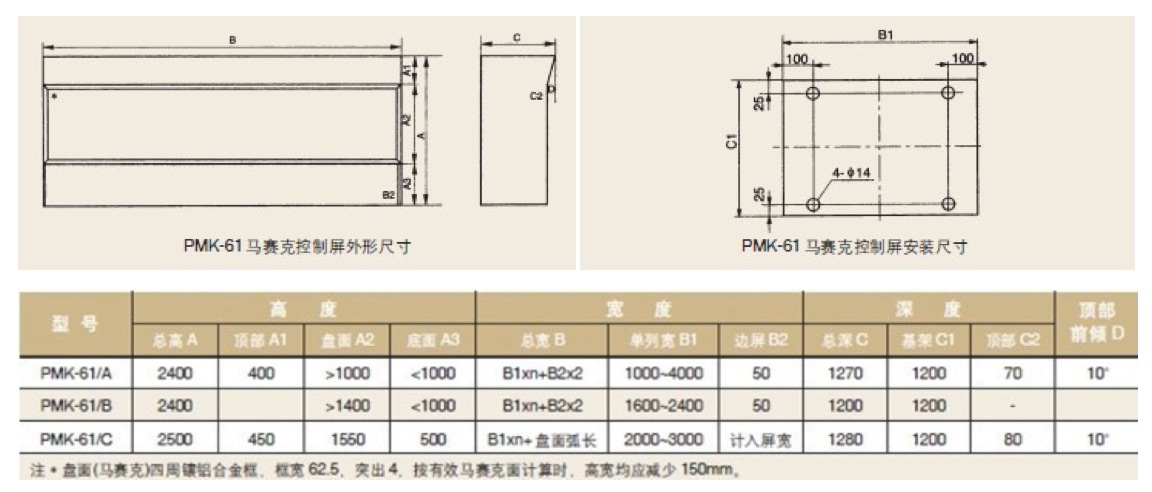 4.3 The mosaic simulation screen structure is wall mounted< br>
5. Ordering instructions
4.3 The mosaic simulation screen structure is wall mounted< br>
5. Ordering instructions
5.1 Provide a complete set of engineering drawings, including general layout drawings, instrument unit wiring diagrams, terminal strip diagrams, etc< br>
5.2 Select the overall dimensions of the frame, screen module color, and screen frame color< br>
5.3 Specify product name, quantity, and specifications< br>
5.4 Prepare an order list according to the drawings as an attachment to the contract< br>
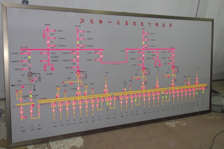
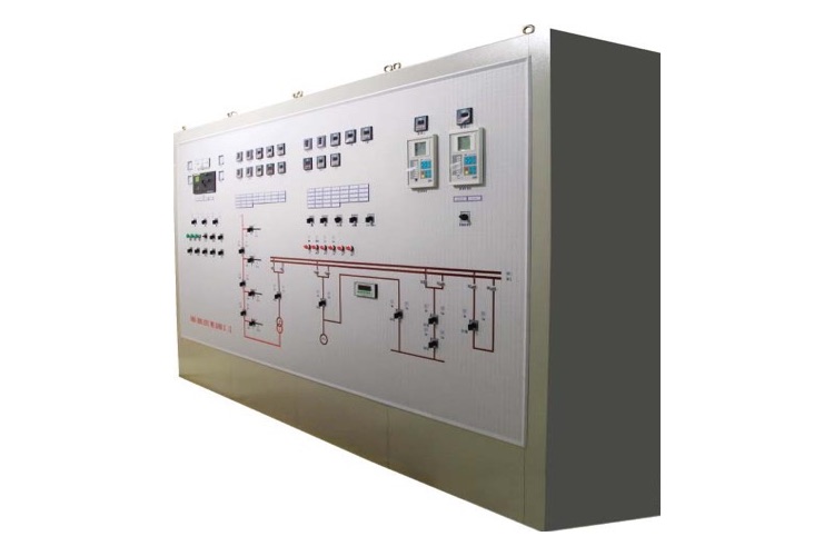
1. Application scope:
The DBJ type multifunctional signal alarm device (hereinafter referred to as the "device") is suitable for substations, power plants, wind/solar power generation, ships, oil and gas platforms, petrochemical and other systems. It is a multifunctional comprehensive alarm device that organically combines the functions of accident/warning signals, security, inspection, and reset in previous systems for centralized signal processing. For small-scale computer stations in remote areas, wireless remote transmission devices can be combined to achieve remote alarm monitoring< br>
2. Function implementation:
1. Signal input: With or without an empty contact input, after filtering, amplitude discrimination, width discrimination, delay and other logic, the local signal is activated to emit an audible and visual alarm signal< br>
2. Signal output: With up to 16 following relay output contacts, 1 total alarm and 1 device fault alarm output contact< br>
3. Communication function: The device has an RS485 communication interface, which can upload real-time information processed and executed to the upper computer< br>
4. logic programming: the device is equipped with a programming interface, and the input and output are logically configured through the dedicated APP of PC or PDA< br>
3. Technical parameters
1. Environmental parameters:
Atmospheric pressure: within the range of 86~106kPa
Working temperature: -10 ℃~55 ℃
Relative humidity: 20%~95% without condensation
Storage and transportation temperature -20 ℃~65 ℃
2. Electrical parameters
Device working voltage range Vn: 85~265VAC/100~370VDC
Follow relay output contact capacity 250VAC/5A 30VDC/1A
Maximum power consumption of the device: less than 10W. The recommended value for external protection fuse is 2A/250V slow break< br>
Insulation resistance: greater than 20M Ω/500V
Dielectric strength: 1000V/1mA
The power interruption should not be less than 250ms and adapt to voltage crossing characteristics
Immunity test meets level 3
4、 Structure and installation
Structure: The overall material is made of aluminum alloy material combined with plastic parts, and the panel is coated with plastic film, with a smooth and delicate surface that is rich in texture. The indicator signal lights on the corresponding panel of the alarm circuit display clearly and intuitively< br>
Installation: The device adopts embedded installation, and each circuit connection adopts plug-in terminals, which is convenient for future product maintenance< br>
Operation: The panel button operation settings include Test (TST), Mute (MUTE), and Confirm (ACK) buttons, combined with flashing indicator lights, with clear functions and easy to understand operation< br>
Outline dimensions and installation hole drawings (device outline dimensions 144 * 144 * 150mm)
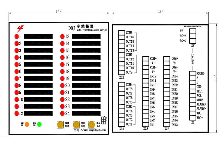 5、 Function keys and instructions for use
1. Definition of panel function keys
Keyboard definition
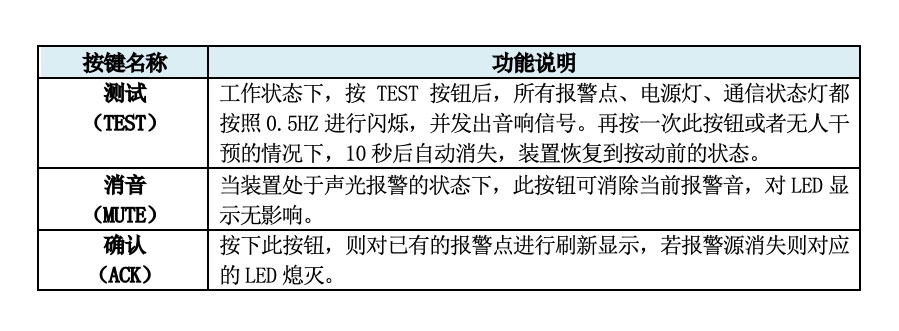 Definition of LED lights
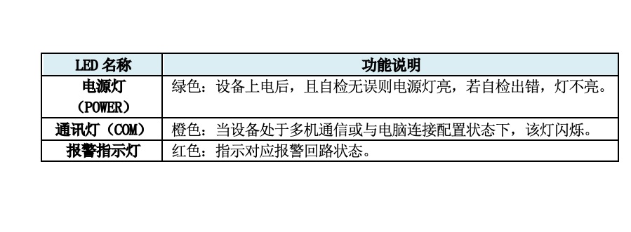 2. Terminal definition and principle wiring, terminal strip definition behind the device
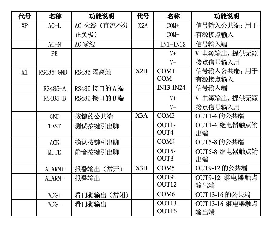 3.Terminal principle wiring diagram
 3. instructions
Device workflow
After the device is powered on, run the self check program. After the self check is correct, the power light will light up normally, otherwise the power light will not light up< br>
When the device communicates with multiple machines through the RS485 interface or logically configures the device itself through the configuration port, the communication light flashes according to the communication data flow (010110...)< br>
F2A alarm program action process:
After the first alarm (in chronological order, the first alarm point), the light signal flashes and an audio signal is emitted. After pressing the ACK button, if the alarm point disappears, the light signal and audio signal disappear. After pressing the ACK button, if the alarm point does not disappear, the light signal remains on and the audio signal disappears< br>
After subsequent alarms (in chronological order, for all alarm points except one), the light signal remains on and an audio signal is emitted. After pressing the ACK button, if the alarm point disappears, the light signal and audio signal disappear. After pressing the ACK button, if the alarm point does not disappear, the light signal remains on and the audio signal disappears. After the alarm point is generated, if no one intervenes, the audio signal will automatically disappear after 20 minutes, and the optical signal will remain in the state after the alarm point is generated
After pressing the ACK button, if the alarm point does not disappear, the light signal remains on and the audio signal disappears. In this case, if the alarm point disappears, there is no need to press any key, and the optical signal disappears with the disappearance of the alarm point< br>
In any state, pressing the MUTE button will cause the audio signal to disappear without affecting the optical signal< br>
In any state, after pressing the TST button, all alarm points, including power lights and communication status lights, will flash at 0.5Hz and emit an audio signal. If no one intervenes, the TST state will automatically disappear after 10 seconds and return to the state before pressing the TST button< br>
6、 Model and selection
The device model consists of 5 parts:
DBJ–D. 0 1 1. 1 1 M / S
① ② ③ ④ ⑤ ⑥ ⑦ ⑧ ⑨
2. Selection instructions:
① Indicates the model, digital multifunctional alarm device
② D: Refers to the digital switching value/empty contact signal input alarm function
A: Indicates the analog signal input alarm function (applicable to central signal alarm in transformer/distribution stations)
③ Switching value (DI) input method 0: passive input; 1: Active input; 2: Analog action current value
④ Switching quantity (DI) input quantity: 16 DI inputs; 2: 24 DI inputs< br>
⑤ 1: With follow-up relay contact output; 0: Without following relay contact output
⑥ The operating voltage range of the device is 1:85~265VAC; 2:100~370VDC
⑦ Switching active input rated voltage 1:110V; 2:220V; 0:48V;< br>
⑧ Communication method RS485 M: Modbus I: IEC60875-5-103
⑨ No markings, suitable for land use; S: Applicable to electrical rooms for ships and offshore oil platform
Example: DBJ-D.110.11M/s represents a multifunctional alarm device suitable for ships with an active input voltage of 110V and 16 switch inputs without following contact output< br>
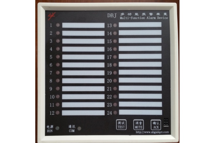 Front view
 dorsal view
 Side View-1
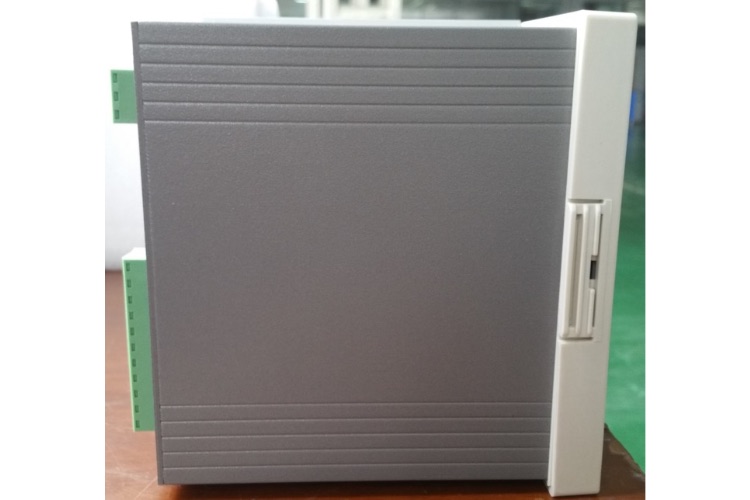 Side View-2
1.1 Overview
This instrument is designed for testing the entire set of battery packs, and different specifications and models have different requirements for the entire set. The specific requirements depend on the instrument. A specialized instrument for testing lead-acid battery packs with a single battery voltage of 1.2V-12V. The instrument adopts the current advanced testing technology principles and has achieved a series of breakthroughs in the research and application of new technologies, new devices, new materials, and new processes. It is a professional testing instrument designed in accordance with relevant national testing and maintenance regulations to perform performance testing on batteries. The instrument has high discharge power, small size, and light weight. The upper computer data management software has complete functions, greatly reducing the workload of daily battery testing and maintenance. Provide comprehensive and scientific testing methods for battery and UPS power maintenance< br>
1.2 Main functional features
The instrument adopts touch screen operation, and the interface can be operated directly using a stylus or finger< br>
There are internal storage and external SD card storage methods for storing data, which can be selected by oneself< br>
It has protection functions such as overvoltage, overcurrent, and overheating< br>
Online monitoring function: Real time monitoring of the battery pack and individual batteries when the battery pack is in online discharge, equalizing charge, floating charge, etc; Including the voltage of the entire group, the voltage of a single battery, the charging and discharging current of the entire group, the charging and discharging capacity of the entire group, and the monitoring time< br>
Discharge test function: After the battery pack is disconnected from the system, use the intelligent fake load for constant current or constant power discharge, or use the intelligent fake load to connect with the user's equipment for constant current discharge. Set parameters such as "discharge current", "discharge time", "discharge capacity", "whole group termination protection voltage", and "single unit termination protection voltage", and the tester will automatically perform the discharge function and display real-time data such as discharge current, discharged battery capacity, whole group voltage, single battery voltage, and discharge time; During the discharge testing process, the discharge parameters can be modified. When the battery pack reaches the set value of termination discharge voltage, termination discharge capacity, termination discharge time, any individual battery voltage below the set value of termination individual voltage, or manual termination operation, the discharge test can be stopped. The termination condition for individual voltage can also be set to only alarm without termination< br>
Capacity quick test function: (optional) After the battery pack is disconnected from the system, the intelligent dummy load is used for discharge, and the actual capacity, internal resistance, and performance status (normal, outdated, degraded) of each battery in the battery pack can be measured in only 3-20 minutes< br>
During the testing process, when an abnormality is detected in the entire or individual battery, or when the tester is working abnormally, the tester automatically terminates the test to protect the battery. The tester adopts an integrated design of monitoring and power parts, and the power part adopts new high-efficiency devices. Humanized operation interface, simple operation, clear process, and simplified Chinese prompts for each step of operation< br>
High brightness color screen LCD display, with clear and beautiful display effect< br>
The upper computer data management software has powerful functions and a friendly interface, providing functions such as data management, printing, analysis, report statistics, and automatic generation of test reports< br>
1.3 Technical indicators:
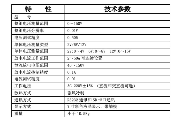 1.4 Introduction to Testing Steps
1.4.1 Online monitoring and testing:
Step 1: Connect the individual voltage collector. (See Chapter 2.4 for details)
Step 2: Connect the entire set of voltage test wires to both ends of the battery pack. (See Chapter 2.5 for details)
Step 3: Insert the power supply and turn on the host< br>
Step 4: Enter the online monitoring parameter settings. (See Chapter 3.1 for details)
Step 5: "Confirm" to start testing< br>
1.4.2 Discharge test:
Step 1: Connect the individual voltage collector (see Chapter 2.4 for details). Pure load does not have this function
Step 2: Turn the discharge switch to the off position (to prevent reverse connection of the discharge cable and damage to the instrument; reverse connection alarm prompt)< br>
Step 3: Connect one end of the discharge wire to the host and the other end to both ends of the battery pack. (Pay attention to red positive, black negative). Reverse connection will result in an alarm prompt. (See Chapter 2.5 for details)
Step 4: Connect the entire set of voltage test wires to terminal 2 of the battery pack< br>
Step 5: Insert the power supply and turn on the host< br>
Step 6: Enter the discharge parameter settings. (See Chapter 3.2 for details)
Step 7: Turn the discharge switch to the closed position< br>
Step 8: "Confirm" to start testing< br>
1.4.3 Capacity quick test (optional function)
Step 1: Connect the individual voltage collector (see Chapter 2.4 for details)< br>
Step 2: Turn the discharge switch to the off position (to prevent reverse connection of the discharge cable and damage to the instrument; reverse connection alarm prompt)< br>
Step 3: Connect one end of the discharge wire to the host and the other end to both ends of the battery pack. (Pay attention to red positive, black negative). Reverse connection will result in an alarm prompt. (See Chapter 2.5 for details)
Step 4: Connect the entire set of voltage test wires to terminal 2 of the battery pack< br>
Step 5: Insert the power supply and turn on the host< br>
Step 6: Enter the parameter settings for capacity quick testing. (See section 3.3 for details)
Step 7: Turn the discharge switch to the closed position< br>
Step 8: "Confirm" to start testing< br>
2.1 Interface Description
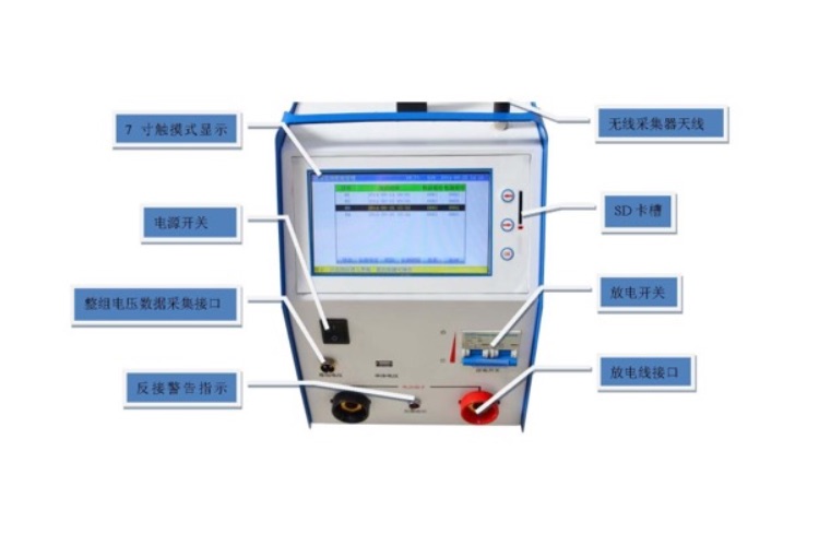
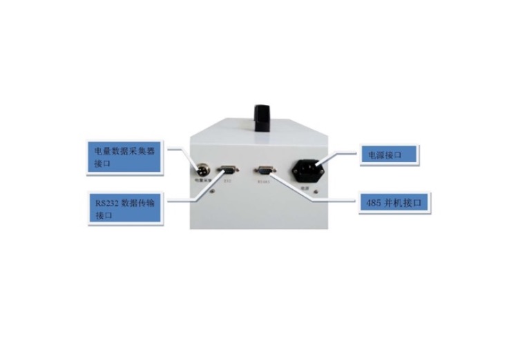 2.2 display screens
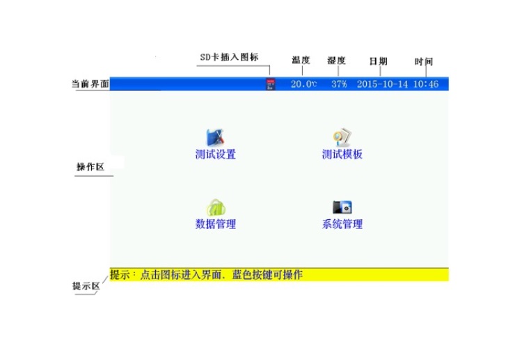 2.3 Easy buttons (can be used when there are problems with the touch)
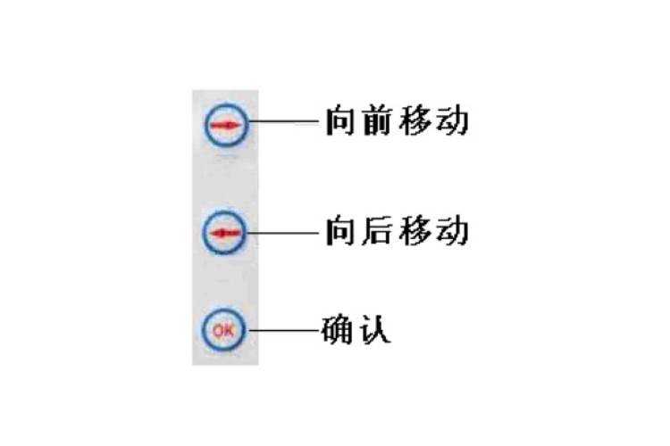 2.4 Single body voltage collector (referred to as single body module) (optional)
2.4.1 There are two communication methods between a single voltage collector and the host:
a. Wireless communication method; The wireless module requires the use of an antenna< br>
It cannot be used in electromagnetic shielding and strong electromagnetic interference situations< br>
The distance range between the host and the wireless individual module should be between 1m and 20m< br>
Be sure to connect the antenna of the host and wireless unit voltage collector properly< br>
b. Wired communication method; Wired modules need to be connected to each other through USB cables< br>
2.4.2 Single modules are divided into two types based on the number of battery sections they can monitor:
a. 24 individual modules< br>
b. 6 individual modules< br>
2.4.3 Single module interface description (taking 24 single modules as an example):
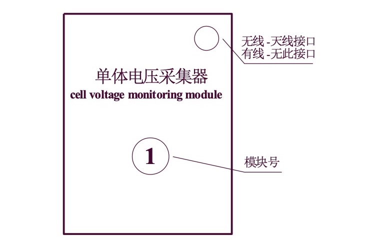 图2.4.3 单体模块正图
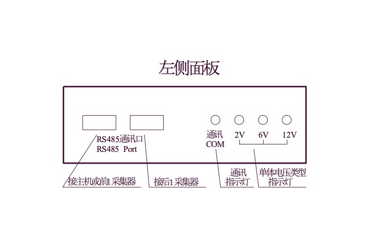
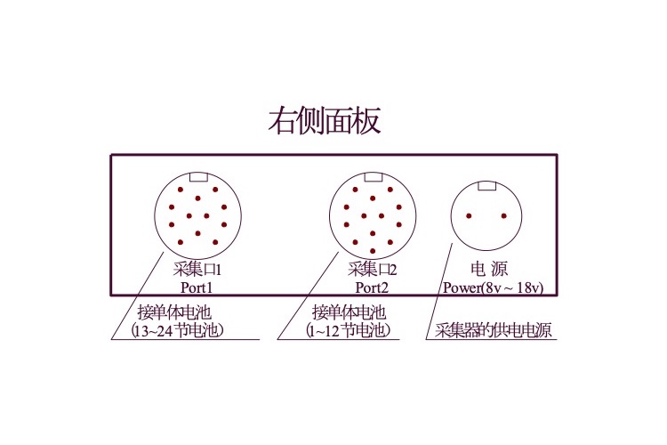 2.4.4 Connection steps for individual modules:
Step 1: Determine the number of individual modules required for the entire battery pack:
Number of modules=total number of battery pack cells ÷ number of monitoring cells per individual module. For undivided modules, the number of modules needs to be increased by 1.
For example, the number of battery cells in a battery pack is 110, and the configured single module can monitor 24 cells. 110 ÷ 24=4.58 cells, which is not evenly divided, so the number of modules required is 5< br>
Step 2: Connect the wiring between the individual module and the battery. (Single module starts from module 1)
The individual module is connected to the individual battery. Please collect and connect according to the corresponding battery number! Connect the acquisition line to the battery first, and then power the module< br>
The sequence of voltage collection line and battery wiring is as follows: starting from the negative pole of the battery pack, and starting from the negative pole of the battery pack, connect in sequence according to "black 00, red 01, red 02- red 23, red 24". When using multiple individual modules, according to the individual module number, connect all the acquisition lines of the individual module from front to back, and do not connect the excess acquisition lines of the last module< br>
After the wiring is completed, first check whether the wiring is correct. After confirming that there are no errors, connect the aviation interface with the "acquisition port 1 and acquisition port 2" of the collector; Acquisition port 1 corresponds to a 12 core harness, and acquisition port 2 corresponds to a 13 core harness< br>
The power supply for the individual module is "8V~18V", which is supplied separately by the power port. Connect the 2-core power cord to the "8V~18V" power supply, and ensure that the red positive and black negative are not reversed. Confirm that there is no error and connect the 2-core aviation head to the "power" port of the individual module. The power supply method, if the current measured individual voltage of the battery pack is 2V, is to be powered by 5 batteries; The individual voltage is 6V and is powered by 2 batteries; The individual voltage is 12V and is powered by one battery. Note that each individual module requires power supply< br>
After the individual module is powered on, the individual voltage indicator light on the corresponding module flashes normally< br>
For example:
a. Taking 24 2V batteries as an example, the wiring is as follows
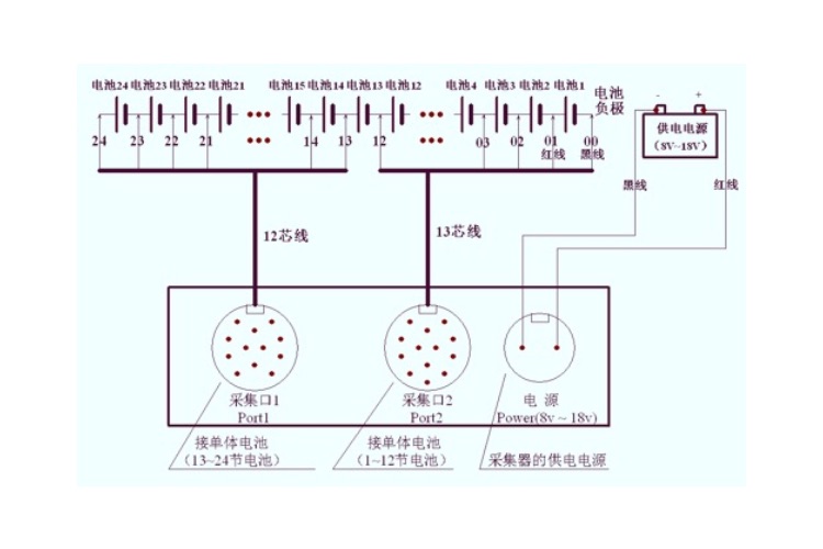 Figure 2.4.4 Connection diagram of 24 2V batteries and 1 single module
b. Taking 8 6V batteries as an example, only the first 9 cells of acquisition port 2 are connected, and the remaining 4 cells do not need to be connected. The wiring is as follows
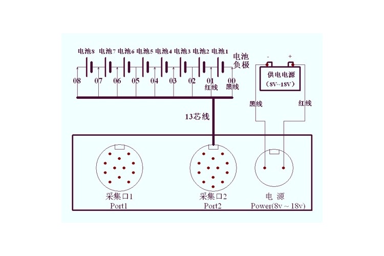 Figure 2.4.4-1 Connection diagram of 8 6V batteries and 1 single module
c. Taking 4 12V batteries as an example, only the first 5 cells of acquisition port 2 are connected, and the remaining 8 cells do not need to be connected. The wiring is as follows:
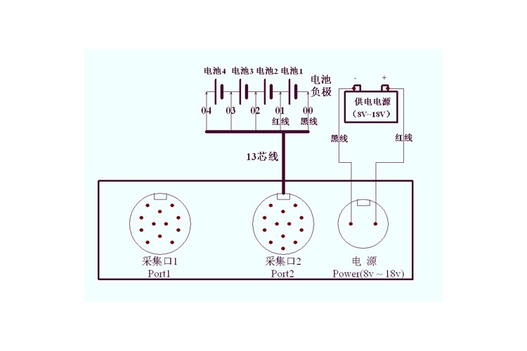 Figure 2.4.4- Connection diagram of 4 12V batteries and 1 single module
d. If the entire set of 220V batteries has 110 2V batteries, the required modules for calculation are 110 ÷ 24=4.58, requiring 5 modules, and only 14 batteries need to be tested for the last module; Connect the communication interface with the following wiring
 Figure 2.4.4-3 Connection diagram of multiple individual modules and batteries
Step 3: If the individual module is wired for communication, please connect the USB cable to each individual module and the host; Please connect the antenna wirelessly
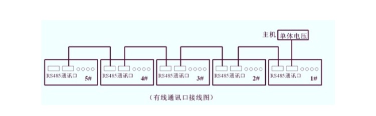 . 5 Host Wiring Instructions
2.5.1 Wiring and dismantling principles
Before testing, the wiring should be carried out in the order of "instrument first, then battery", that is, the wiring at the instrument end should be connected first, and then the wiring at the battery end< br>
After the test is completed, the user should remove the cables in the order of "battery first, instrument later", that is, first remove the wiring at the battery end, and then remove the connection at the instrument end< br>
2.5.2 Connection of discharge cables
The discharge cable connects the "discharge current interface" of the tester to the battery pack< br>
Note: "positive" (red) is connected to the positive pole of the battery pack, and "negative" (black) is connected to the negative pole of the battery pack. Do not reverse connect< br>
2.5.3 Connection of the entire set of voltage collection lines
Connect the entire set of voltage collection wires of the tester to the positive and negative terminals of the battery pack< br>
Note: The "positive" (red clip) of the entire voltage line is connected to the positive pole of the battery pack, and the "negative" (black clip is connected to the negative pole of the battery pack. Reverse connection is strictly prohibited!
2.5.4 Connect the 220V power cord of the tester. Not connected when using DC power supply< br>
2.5.5 Please carefully check if the wiring is correct, pay attention to whether the positive and negative terminals of the battery terminal, voltage collection line terminal, and discharge current terminal are correctly connected, and reverse connection is strictly prohibited< br>
After checking without any errors, connect the power supply and the tester starts working
2.6 Electricity collection (optional)
When the tester is working in online monitoring, the electricity collector is used to monitor the charging and discharging current of the battery pack< br>
The tester works during discharge testing, and the electricity collector is used to test the discharge current of user equipment< br>
The direction indicated by the power collector is the charging current direction of the battery pack, please do not connect it in the opposite direction
2.7 Parallel wiring (optional)
Two instruments must be available< br>
Each instrument is connected to a test line separately< br>
Connect the two instruments together through the RS485 interface< br>
Set one as the host,; The other one is set as a slave (see Chapter 3.12 for details).
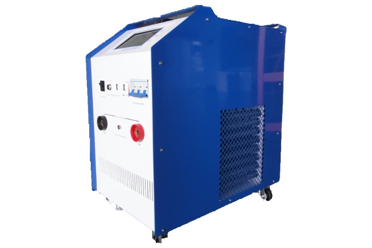
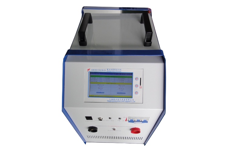
Shanghai Genxing Electric Power Equipment Co., Ltd. has successfully completed the construction of the PBY series intelligent emergency power supply system equipment in the Huangpu Campus of Fudan University Affiliated Obstetrics and Gynecology Hospital. Based on the current electricity consumption situation in the Huangpu Campus and the suggestions of your hospital's electrical engineers, we have tailored special specifications of products for the hospital according to the most reasonable configuration principle
At present, the project has been fully completed, and the entire PBY intelligent emergency power system was officially put into operation on April 18, 2017. At this point, the hospital has an independent third-party intelligent emergency power system, providing strong protection for the electricity consumption of important departments, ensuring the safety of the hospital and benefiting more patients
Schematic diagram of the three-dimensional placement of PBY rack equipment in the newly built PBY distribution room
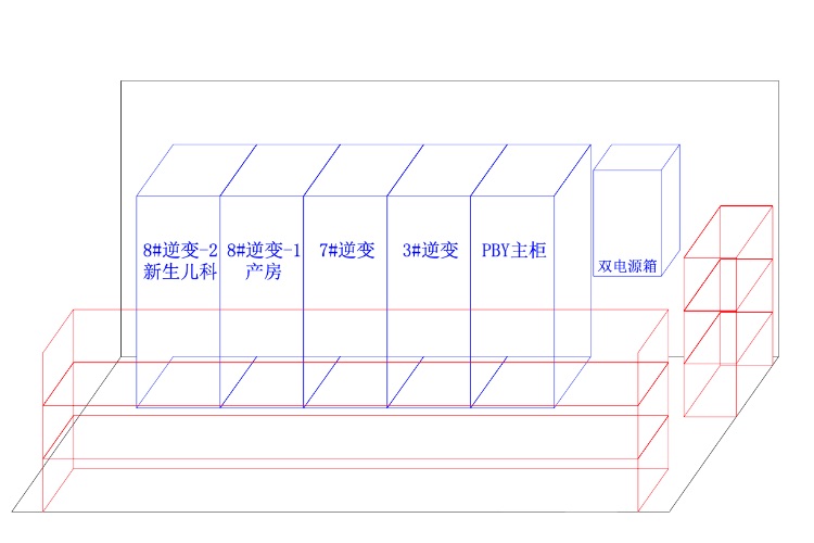
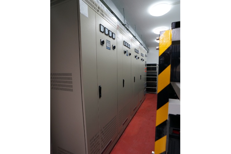

Shanghai Genxing Electric Power Equipment Co., Ltd. focuses on the current power supply situation of the operating room, intensive care unit, emergency, hemodialysis, information and monitoring, and pediatric departments in the newly built building of the Affiliated Obstetrics and Gynecology Hospital of Jiaotong University (with a rated capacity of 150KVA and normal emergency discharge for 3 hours). Considering the weight, installation area, and convenience of operation and maintenance of the newly added equipment, combined with the existing area of the equipment room and the actual load, And according to the principle of redundant design, that is, after the external power supply disappears, we choose the PBY large capacity uninterrupted power supply model as PBY-150/1000/380 (220) -1-1-104-PB; Two three-phase modes with an output voltage of 380V, and three single-phase modes with an output voltage of 220V; The battery adopts the internationally leading Shengyang battery, with a voltage of 2V per cell and a capacity of 1000AH; 5 inverters with an output power of 30KVA are used, with a total output power of 150KVA; The output current is 680A (effective value); A complete set of third-party intelligent emergency power supply scheme is composed of one integrated monitoring, operation and charging cabinet, five inverter power cabinets and a group of 104 batteries
Layout diagram of PBY equipment room
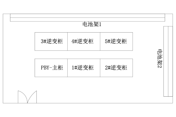
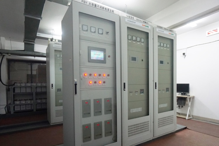
The PBY series intelligent emergency power supply system independently developed and developed by Shanghai Genxing Electric Power Equipment Co., Ltd. is an important basic equipment that can provide long-term AC power supply for important electric fields such as hospitals, power systems, finance, chemical, industrial systems, etc. after the power outage< br> Shanghai Genxing Electric Power Equipment Co., Ltd. is targeting the current power supply situation of the operating room and intensive care unit of the newly built hospital for maternal and child health in Jiading (requiring a rated capacity of 80KW and continuous discharge for about 1 hour). We have chosen the PBY large capacity uninterruptible power supply model as PBY-80/600/220-1-1-104-PB; Single phase mode with an output voltage of 220V; Two 30KW inverter power supplies and one 20KW inverter power supply are used, with a total output power of 80KW; The maximum output current is 363 A; A complete set of third-party backup emergency power supply scheme is composed of one integrated monitoring, operation and charging cabinet, three inverter power cabinets and a group of 104 batteries
PBY equipment is placed on the Mechanical floor of the new Jiading Maternal and Child Health Care Hospital, and its specific dimensions are as follows:
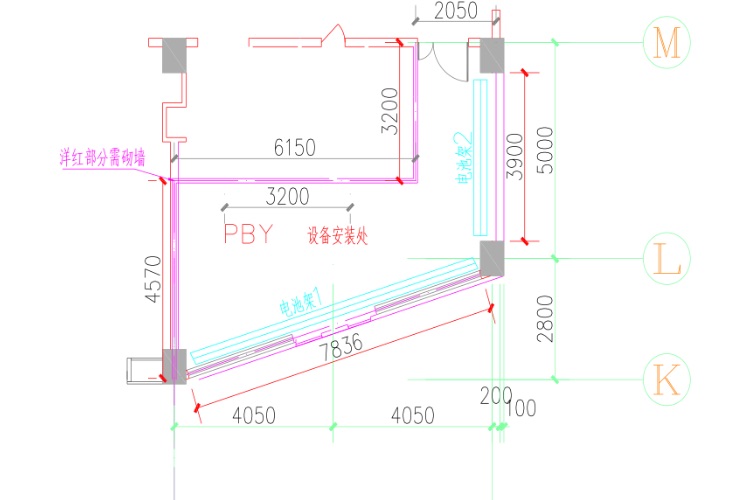
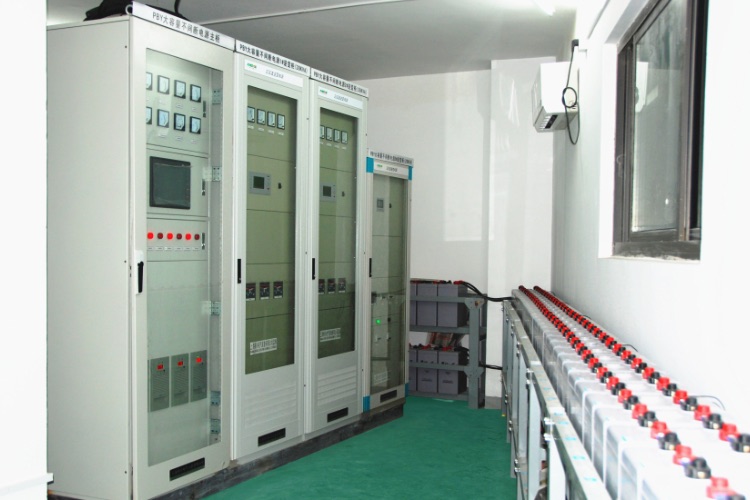
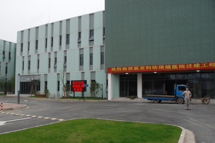
China Wire and Cable Import and Export Co., Ltd. has entrusted Shanghai Genxing Electric Power Equipment Co., Ltd. to produce and process four 161KV busbar differential screens for two 161KV substations (renovation) projects in Ghana< br>
1. Basic requirements
The equipment and components provided by Shanghai Genxing Electric Power Equipment Co., Ltd. should comply with the latest versions of the following standards. In case of inconsistency with the following standards, the higher standard shall prevail< br>
1. IEC60068-2-1 Environmental conditions
2. IEC60255-21-1 Mechanical conditions
3. IEC60255-5 insulation
4. IEC60255-11 AC ripple in DC power supply
5. IEC60255-22-1 Class III high-frequency interference
6. IEC60255-22-4 Class IV fast transient interference
7. IEC60255-22-2 Class III electrostatic discharge
8. IEC60529 Dust Prevention
9. GB: Chinese National Standard
10. DL: China Power Industry Standard
11. JB 5777.2-91 Chinese Machinery Industry Standard
12. ISO: International Association for Standardization
2.1 Environmental conditions of substations
2.1.1 Surrounding air temperature
(1) Environmental temperature
Upper limit: 45 ℃
Lower limit: -5 ℃
Average annual temperature: 30 ℃
(2) Ability to withstand earthquakes
Horizontal acceleration: 0.3g
Vertical acceleration: 0.15g
2.1.2 Altitude:<1000m
2.1.3 Maximum wind speed: 34m/s
2.1.4 Environmental relative humidity:
Relative humidity: ≤ 98%
2.1.5 Air pollution: dust, salt mist, chemical pollution, etc.
2.1.6 Seismic intensity: 7 degrees
The provided equipment should meet the requirements of the contract documents and work safely and reliably under the above environmental conditions< br>
2.2 Engineering conditions:
2.2.1 System Overview
System voltage: 161KV/33KV/11KV
Maximum system voltage: 170KV/36KV/12KV
System rated frequency: 50Hz
System neutral grounding method: The neutral points of 161KV, 33Kv, and 11KV system transformers are directly grounded
2.2.2 Installation location: indoor control room
2.3 Technical Requirements
The structure of the busbar differential protection screen should ensure the safety of personnel and facilitate operation, maintenance, inspection, repair, and testing< br>
2.3.2 Each component of the busbar differential protection screen should comply with their respective technical standards, and components with the same rated value and structure within the same type of product should be interchangeable. All equipment inside the screen should meet the requirements of the humid zone and be evaluated according to the requirements of the humid zone< br>
2.3.3 The busbar differential protection screen must be an independent fully enclosed structure with a base. The rear door is used, and the protection level of the shell is IP4X. The small busbar perforation adopts a sealing plate structure, and the sealing plate is fixed with bolts. The small busbar is made of copper rods with an insulated sheath< br>
2.3.4 Cabinet size: width × deep × High
The standard size of the protective screen is 800mm × 600mm × 2260mm (including base 60mm)
The manufacturer must strictly follow the order drawings for production and shall not make modifications without the written consent of the design< br>
2.3.5 The color of the busbar differential protection screen shall be light gray, with a color code of RAL 7032. The thickness of the steel plate on the casing of the busbar differential protection screen shall not be less than 2mm.
2.3.6 The secondary wiring phase inside the screen is arranged from left to right and from top to bottom facing the busbar differential protection screen as R (A), Y (B), B (C), and color coded (Red Yellow Blue).
The production technology department of Shanghai Genxing Electric Power Equipment Co., Ltd. has successfully completed the design, screen assembly, debugging, factory inspection, and shipment of the AKOSOMBO and VOLTA bus differential protection cabinets for the 330kV WAPP Coastal Transmission Backbone Project in Ghana after a stage of effort. And smoothly put into operation throughout the entire substation project at once.
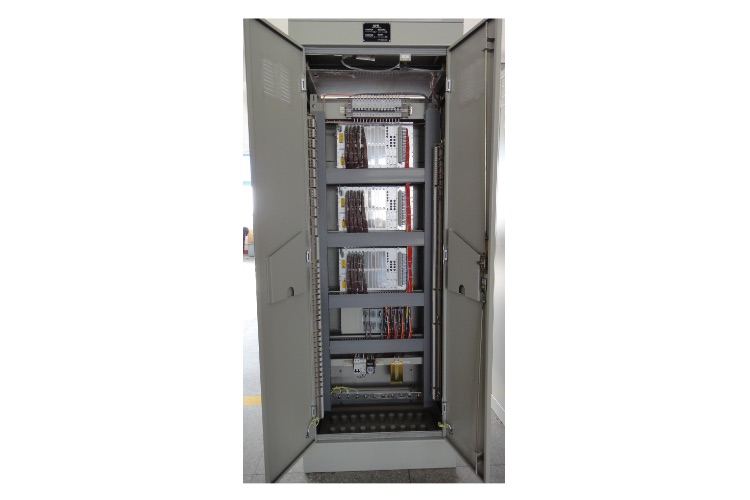
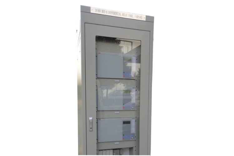
Zhongdian International Technology Co., Ltd. has entrusted Shanghai Genxing Electric Power Equipment Co., Ltd. to produce and process two sets of 110V350AH, one set of PLC program controlled AC screen system, and a batch of terminal boxes for the Nigeria project.
This project is located in southeastern Nigeria, where the 330/132/33kV ONITSHA substation is an expansion station, 330kV is connected with one and a half circuit breakers, 132kV is connected with double buses, and 33kV is connected with single bus sections. This project will expand one 100MVA 132/33kV main transformer room and three 33kV outgoing lines. One 300kVA, 33/0.415kV grounding transformer is installed in the station, 100kW station power is provided, and one 0.415kV diesel generator is used as standby power supply.
Our company's engineers have successfully completed the design, production, commissioning, factory inspection, and shipment of all equipment according to the technical agreements for AC/DC screens and terminal boxes, and have fully communicated with engineers from Hebei Survey and Design Institute.
The project has been in operation for some time now, and the AC/DC screen and terminal box equipment provided by our company operate stably and reliably, receiving unanimous praise from the owner.
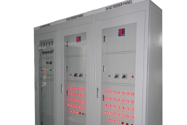
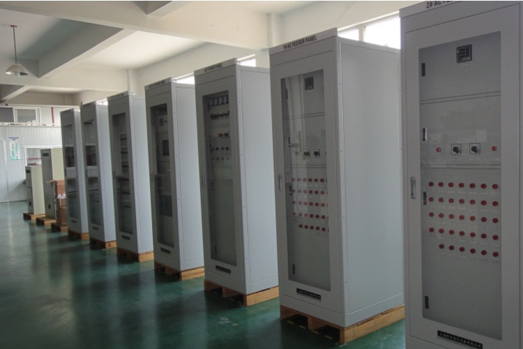
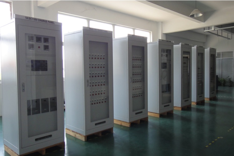
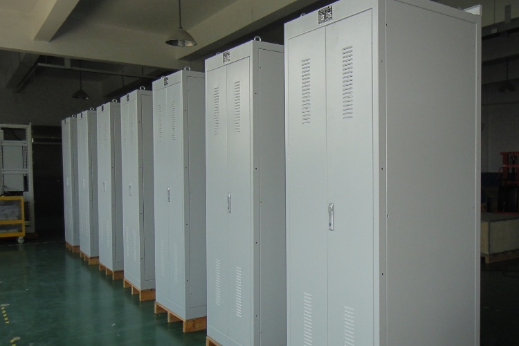

需要40字以内的描述

需要40字以内的描述

需要40字以内的描述.
需要40字以内的描述.
40 word description required.
Require a description of no more than 40 words.